
User Manual


7
0200018-J0 Rev C
1
3
5
2
4
6
7
8
*
A
U
X
I
L
I
A
R
Y
S
W
I
T
C
H
A
1
A
2
A
3
A
4
A
5
A
6
A
7
A
8
A
1
A
3
A
5
A
7
A
2
A
4
A
6
A
8
#
1
4
A
W
G
R
E
D
*
*
C
L
O
S
E
D
B
E
T
W
E
E
N
P
O
S
I
T
IO
N
S
N
O
R
M
B
Y
P
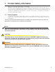
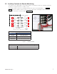
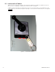
Figure 1 — Auxiliary contacts
3.2 Auxiliary Contacts for Remote Monitoring
The operation of the Alpha MBS is "make-before-break". The auxiliary contacts are available to generate
an alarm if a "caught in transition" condition occurs.
The auxiliary switch contacts are located below TB3 in the interior of the Alpha MBS – see Figure 1.
Table A shows the condition of these contacts for all possible states of the bypass switch.
The System Schematic is shown in Chapter 6 on page 14.
Table A — Auxiliary switch truth table
MBS Function
BYPASS A1-A2 (BYP) Closed
UPS A3-A4 (UPS) Closed
CAUGHT IN
TRANSITION
A5-A6 Closed between positions
A7-A8 Closed between positions
Table B — Auxiliary Contacts – Electrical Ratings
Voltage Rating
250 Vac (max)
Current Rating
15 A