Alpha 255A External Maintenance Bypass Switch for Uninterruptible Power Supply Systems Installation & Operation Manual Part # 0200018-J0 Effective: 01/2012 member of The Group™ Your Power Solutions Partner
Alpha 255A External Maintenance Bypass Switch for Uninterruptible Power Supply Systems NOTE: Photographs contained in this manual are for illustrative purposes only. These photographs may not match your installation. NOTE: Operator is cautioned to review the drawings and illustrations contained in this manual before proceeding. If there are questions regarding the safe operation of this powering system, contact Alpha Technologies or your nearest Alpha representative.
Table of Contents 1. Product Safety Information ���������������������������������������������������������������������������������������������������3 1.1 Safety Symbols �������������������������������������������������������������������������������������������������������������������������� 3 1.2 General Warning and Cautions �������������������������������������������������������������������������������������������������� 4 1.
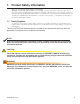
1. Product Safety Information SAVE THESE INSTRUCTIONS: This manual contains important safety instruc- tions that must be followed during the installation, servicing, and maintenance of the product. Keep it in a safe place. Review the drawings and illustrations contained in this manual before proceeding. If there are any questions regarding the safe installation or operation of this product, contact Alpha Technologies or the nearest Alpha representative. 1.
1.2 General Warning and Cautions WARNING! You must read and understand the following warnings before installing the Alpha MBS and its components. Failure to do so could result in personal injury or death. 1.3 • Read and follow all instructions included in this manual. • Do not work alone under hazardous conditions. • Only qualified personnel are allowed to install, operate and service this system and its components. • Before proceeding, read this manual and be sure you understand its intent.
2. Introduction 2.1 What this Manual Covers This manual provides full procedures for the safe and proper installation and operation of the Alpha External Maintenance Bypass Switch (Alpha MBS) with meter controlled solenoid lockout. 2.
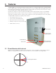
3. Features The Alpha MBS is a manually operated mechanical switch for use with the Alpha series of Uninterruptible Power Supplies (UPS). It provides a simple and effective means for bypassing uninterruptible power supplies (UPS) while maintaining continuity of power to critical loads. (A schematic at the end of the manual shows the MBS with the Alpha AMPS80 HP power system.) Normally the output to the critical load is powered by the UPS with the bypass switch in the NORMAL (UPS) position.
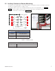
3.2 Auxiliary Contacts for Remote Monitoring The operation of the Alpha MBS is "make-before-break". The auxiliary contacts are available to generate an alarm if a "caught in transition" condition occurs. The auxiliary switch contacts are located below TB3 in the interior of the Alpha MBS – see Figure 1. Table A shows the condition of these contacts for all possible states of the bypass switch. The System Schematic is shown in Chapter 6 on page 14.
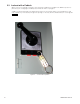
3.3 Lockout with a Padlock When someone is working on the UPS, they may want to padlock the handle in the BYPASS position to prevent anyone changing the handle position while the work is in progress. A padlock can be attached to the red bar at the bottom of the manual switch. Push the red bar in, and route a padlock (or lockout bar) through the openings on the face, down toward the bottom of the legend (Figure 2).
4. Pre-Installation 4.1 Unpacking Before unpacking the product, note any damage to the shipping container. Unpack the product and inspect the exterior for damage. If any damage is observed, contact the carrier immediately. Continue the inspection for any internal damage. In the unlikely event of internal damage, inform the carrier and contact Alpha Technologies for advice on the impact of any damage: 1 888 462-7487 4.1.1 Returns for Service Save the original shipping container.
4.2 4.2.1 Site Planning Mounting Consult local electrical codes to determine a suitable location for mounting the Alpha MBS. Use the dimensions in Figure 3 to wall mount the Alpha MBS with adequate clearance from the adjoining wall. 0.50in 12.7mm X4 MOUNTING HOLES 0.75in 19.1mm 24.00in 609.6mm 0.75in 19.1mm 0.75in 19.1mm 36.00in 914.4mm Alpha MBS Front View 12.00in 304.8mm DISTANCE TO WALL OR EQUIPMENT 0.75in 19.1mm Figure 3 — Alpha MBS mounting diagram 4.2.
5. Installation WARNING! Make sure that you have read and understood all the information given in "Product Safety Information" on page 3. CAUTION! Always operate the switch with a quick continuous motion, do not hold it in mid-position. CAUTION! DO NOT operate the bypass switch while the UPS is in inverter mode (front display on the UPS shows INVERTER). CAUTION! Operating with the inputs out of phase could cause damage to the critical loads. 5.
5.2 Wiring the Alpha MBS WARNING! Ensure the wire size, circuit breakers, and fuses are sized according to the applicable electrical code and LIMIT THE SHORT CIRCUIT CURRENT TO 5000A. WARNING! Use minimum 75 ºC rated wire. CAUTION! The terminal blocks in the Alpha MBS are suitable for a single #6 AWG wire and up to 350 kcmil wire. Alpha MBS UPS System Utility TB2 Over Current current limiting device TB1 Critical Loads TB3 Torque the terminal blocks to 31 N-m (275 in-lbs).
NOTE: Phase detection is measured between TB2-L1 and TB3-L1. See the "System Schematic" on page 14. For a single-phase installation, ALWAYS USE L1 on all terminal blocks (TB1, TB2, TB3). For a 2-pole installation, use L1 for one line on all terminal blocks. Procedure Figure 7 shows two typical configurations for wiring the Alpha MBS into an UPS system. 1. Use a #6 AWG wire and up to 350 kcmil wire (minimum 75 ºC rating) to connect the Alpha MBS and UPS to the utility line.
14 NOTES: RED GROUND TB3: UTILITY TB2: UPS 2. 2 1 9 R1 1 5 1 NEUTRAL IS BUSSED AT TERMINALS 2 A Y PL4: "UPS L1" F1: 2A USE CL.CC FNQ-R-2 OR EQUAL 6 3 2 3 6 4 PHASE METER Y 4 3 P2 PM P1 P5 1 1 5 1/2 A PL5: "UPS L2" F2: 1/2A USE CL.CC FNQ-R-1/2 OR EQUAL 1/2 A B 2 Y PL6: "UPS L3" F3: 1/2A USE CL.CC FNQ-R-1/2 OR EQUAL 2 A F5: 1/2A USE CL.CC FNQ-R-1/2 OR EQUAL 14 1/2 A Y PL2: "UTILITY L2" R1 13 F6: 1/2A USE CL.
7. Operations CAUTION! The NORMAL/ BYPASS switch position cannot be changed if power is not present from either power source. The Alpha MBS operates normally if at least one power source is present. See Table A. CAUTION! The MANUAL OVERRIDE key can be used to change the source selection of the Alpha MBS even when the inputs are out-of-phase condition. Operating with the inputs out of phase could cause damage to the critical loads. 1.
8. Troubleshooting 8.1 Manual Release of Bypass Switch Solenoid WARNING! Do NOT perform this procedure if power is present at the switch. The NORMAL/ BYPASS switch position cannot be changed if power is not present from either power source. Use the following procedure to release the bypass switch solenoid if a situation arises where all power is lost and it is necessary to change the position of the switch. 1. Release the solenoid by inserting a non-conductive device (plastic pen, e.
9. Specifications Alpha MBS Specifications and Approvals Model Number 0200018 Alpha MBS – Mechanical Specifications Dimensions, cm (in) HxWxD 91 x 61 x 28 (36 x 24 x 11) Weight, kg (lb) 79.
10. Warranty Alpha Technologies Ltd. warrants all equipment manufactured by it to be free from defects in parts and labor, for a period of two years from the date of shipment from the factory. The warranty provides for repairing, replacing or issuing credit (at Alpha’s discretion) for any equipment manufactured by it and returned by the customer to the factory or other authorized location during the warranty period. There are limitations to this warranty coverage.
CSA/NRTL — MARKS — BACKGROUND What are the CSA and NRTL? CSA (Canadian Standards Association also known as CSA International) was established in 1919 as an independent testing laboratory in Canada. CSA received its recognition as an NRTL (Nationally Recognized Testing Laboratory) in 1992 from OSHA (Occupational Safety and Health Administration) in the United States of America (Docket No. NRTL-2-92). This was expanded and renewed in 1997, 1999, and 2001.
Alpha Technologies Ltd. 7700 Riverfront Gate Burnaby, BC V5J 5M4 Canada Tel: +1 604 436 5900 Fax: +1 604 436 1233 Toll Free: +1 800 667 8743 Alpha Technologies Inc. 3767 Alpha Way Bellingham, WA 98226 United States Tel: +1 360 647 2360 Fax: +1 360 671 4936 Alpha Industrial Power Inc.