
Instruction manual


Page 14 Chapter Four
Eagle 450 Upgrade Instructions, Rev. A00
To enable remote reset through serial port 0, you must do two things:
1.
Install the JP1 jumper. The factory default is not installed.
2.
Connect a push-button switch between pin-1 and pin-7 (signal ground) at the terminal end of the
terminal cable attached to serial port 0.
Once you’ve enabled remote reset, you can reset the computer by activating the push-button switch.
The remote reset adapter allows you to reboot the computer from anywhere in your facility by wiring an
external switch to the location you want. To install the remote reset adapter, follow the instructions in
PDI-10323-00. The JP1 jumper must
not
be installed. Attach the adapter’s single-wire connector to the
connector labeled RESET at location P8. Attach it to the pin away from the edge of the board.
INSTALLING THE SSD CHIP
If you are upgrading from an Eagle 100, 300 or 500, you must remove the SSD chip from your existing
computer and install it in on the AM-138. If you are upgrading from an AM-1600, your upgrade kit
includes a new SSD chip, which you must install in the AM-138.
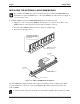
Removing the SSD requires a special tool. See the illustration below for more information.
The SSD chip and boot
PROM on the AM-138
board require a
specialized tool for
their removal. If you
attempt to remove
the SSD chip or
boot PROM using
a screwdriver or
pocketknife, you
could easily damage
both the chip and the
socket. This type of chip
extraction tool is available
at retail stores specializing
in electronic components.
WARNING!
Figure 4-2: SSD Chip Removal Tool