Operating Manual UK Brine/Water Compact Heat Pumps SWC – Series We reserve the right to modify technical specifications without prior notice.
Please read first Symbols This operating manual provides important information on the handling of the unit. It is an integral part of the product and must be stored so that it is accessible in the immediate vicinity of the unit. It must remain available throughout the entire service life of the unit. It must be handed over to subsequent owners or operators of the unit. The symbols used in the operating manual have the following meaning: Read the operating manual before working on or operating the unit.
Contents Information for operators and qualified technicians Please read first............................................................................... 2 Symbols................................................................................................... 2 Intended use....................................................................................... 4 Exclusion of liability.................................................................. 4 EC conformity.....................................
Intended use Safety The unit may be used only for the intended use. This means: The unit is operational safe when used for the intended purpose. The construction and design of the unit conform to the state of the art, all relevant DIN/VDE regulations and all relevant safety regulations. • for heating. • for heating hot water. • for cooling. (Availability of the cooling function depends on the model). “Cooling function” section. The unit may be operated only within its technical parameters.
Customer service For technical assistance, contact the factory customer service department or the manufacturer’s local service partner. Overview “Customer service”. Warranty / Guarantee For warranty and guarantee conditions, please refer to the purchase documents. Notice: Please contact your dealer concerning warranties and guarantees.
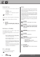
Functioning principle of the heat pump system In a closed circuit, an environmentally compatible refrigerant is successively vaporized, condensed and liquefied. The increase in pressure resulting from this process also causes the temperature of the refrigerant to rise. This generates high temperatures suitable for heating, for example by means of floor or wall heating, or through radiators.
Cooling function The cooling function is available only for heat pumps with the model designator K. THE ROOM THERMOSTAT FOR THE COOLING FUNCTION The room thermostat is used to switch the cooling function on and off: It is not possible to retrofit heat pumps for cooling without this designator. For the model designator, please refer to the purchase documents. It is also on the rating plate attached to the outside of the unit.
Care of the unit The outer surfaces of the unit can be cleaned with a damp cloth and household cleaning products. Do not use cleaning or care products that contain abrasives, acids and/or chlorine. Such products would destroy the surfaces and could also damage the technical components of the unit. Maintenance of the unit The cooling circuit of the heat pump requires no regular maintenance.
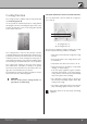
Scope of delivery Installation and assembly Example of scope of delivery: Observe the following when performing all work: Notice: Always comply with applicable accident prevention regulations, with applicable statutory regulations, ordinances and directives. Warning! The heat pump or heat pump system may be installed and assembled only by a qualified technician! Notice: Observe the sound levels of the respective model. Overview “Technical data/scope of delivery”, “Sound” section.
Danger! The unit can tip when being removed from the wooden pallet and during transport with a hand truck. This can result in personal injury and damage to the unit. Installation Danger! Several people are required to install the unit. – Take suitable precautionary measures to eliminate the danger of tipping. Notice: We recommend removing the front panel to reduce the weight of the unit for further transport. Loosen quick-release screws for the front panel.
Warning! Hands and fingers could be crushed during the following tasks! Secure unit in raised position so that it cannot accidentally tip back into the original position. • Place one sylomer strip flush with the respective outer edge of the unit… Installation of the hydraulic connections Caution. The heat source system must be designed according to the specifications of the heat pump guide. Heat pump guide and “Hydraulic connection” instructions.
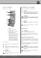
The connections for the heating circuit or the heat source are located on the back of the unit: installation on size 1 units Proceed as follows: We recommend installing a contamination filter (screen size 0.9 mm) on the heat source inflow (return flow) connection… Connect the pipes of the heating circuit and the heat source with the corresponding connections on the back of the unit. Use vibration decouplers. These are included in the scope of delivery.
installation on size 2 units Insulating the hydraulic connections The included compensators must be used for connection to the pipes: The vibration decouplers and the pipes of the heat source must be insulated so that they are sealed against vapor diffusion. The compensators also serve as vibration decouplers. Notice: Insulate in accordance with applicable local standards and directives. Safety components The compensators are packed in the extra box.
Electrical connections Observe the following when performing all work: Danger! Electrical connections may be installed only by qualified electricians. Danger! Observe the relevant EN, VDE and/or applicable local safety regulations during the installation and during all electrical work. Observe the technical connection conditions of the responsible power supply company! Loosen quick-release screws for the front panel. Turn counter-clockwise 90°… 2 Size 2: Switch cabinet closed.
Lay load and control leads in the cable duct inside the unit all the way to the switch cabinet… Caution. Ensure clockwise rotary field of the load power supply. – An incorrect rotary field of the condenser during operation can cause serious, irreparable damage to the condenser. Caution. Make sure to equip the power supply of the heat pump with an all-pole circuit breaker. The all-pole circuit breaker must have a contact gap of at least 3mm. Caution. 1 Size 1: Switch cabinet opened.
Rinsing and filling the unit Size 2: Danger! Unit must be disconnected from the power supply. Open unit if this has not already been done… Electrical connection work and . Obtain overview of the interior of the unit.
Rinsing and filling the heat source Bleeding Contamination and deposits in the heat source can cause malfunctions. Proceed as follows: Proceed as follows: Rinse heat source system thoroughly… Thoroughly mix the anti-freeze agent, available as an accessory, with water at the required ratio.Add only anti-freeze mixed with water to the heat source… Caution. The concentration of anti-freeze in the water must be at least at the level specified for your model.
Bleeding the heat source for a unit with cooling function The bleeding must be conducted manually.
Installation of the heat pump and heating regulator.
Notice: To remove the screen, release the snapin lugs in the reverse order, i.e. from top to bottom, without the use of tools. Caution. The snap-in lugs have a tight fit. Press firmly from the side against the screen toward the middle, so that the snap-in lugs do not break off. Installation of the room thermostat for the cooling function This chapter is relevant for you only if you are using a heat pump with a model designator K. Caution.
Hot-water tank If the heat pump will be used for heating hot water, you must integrate special hot-water tanks in the heat pump system. Notice: The hot-water tank must be equipped with a heat exchanger, which is adapted to the heating capacity of the heat pump. We offer a variety of hot-water tanks for you to choose from. They are optimized for use with your heat pump. Notice: Integrate the hot-water tank in the heat pump system corresponding to the hydraulic diagram for your system.
Commissioning Proceed as follows: The heat pump system will be commissioned by customer service personnel authorized by the manufacturer. There is a fee for commissioning! Conduct a thorough installation inspection and go through the items on the general checklist. “General checklist”. The installation inspection will prevent damage to the heat pump system that could be caused by incorrect installation work. Make sure of the following: • Clockwise rotary field of the load power supply (condenser).
Dismantling Danger! Disconnect unit from power supply before dismantling! Danger! Only qualified electrical technicians are allowed to disconnect the unit from the power supply and de-install all electrical connections. Danger! Only qualified heating or cooling system technicians are allowed to remove the unit from the system. Caution. The anti-freeze mixture of the heat source must not be allowed to enter the sewer system. Collect anti-freeze mixture and dispose of properly.
Technical data/scope of delivery Gerätebezeichnung Heat pump type Brine/water ı Air/water ı Water/water • applicable ı — not applicable Installation location Indoors ı Outdoors • applicable ı — not applicable Conformity Performance data Limits of application Sound CE Heating capacity/COP at B0/W35 Standard point acc. to EN14511 B0/W45 Standard point acc. to EN14511 B0/W35 Standard point acc.
SWC 60H(/K) SWC 70H(/K) SWC 80H(/K) SWC 100H(/K) SWC 120H(/K) • ı — ı — • ı — ı — • ı — ı — • ı — ı — • ı — ı — • ı — • ı — • ı — • ı — • ı — • • • • • — 5,7 ı 4,4 — 6,9 ı 4,4 — 8,9 ı 4,5 — 10,2 ı 4,6 — 11,7 ı 4,5 — — — — — — 5,8 ı 4,7 — 7,0 ı 4,5 — 9,1 ı 4,7 — 10,3 ı 4,7 — 11,9 ı 4,7 20 – 65 20 – 65 20 – 65 20 – 65 20 – 62 -5 – 25 -5 – 25 -5 – 25 -5 – 25 -5 – 25 — — — — B–2 ı W65 40 40 40 40 40 53 53 53 53 53 1000 ı 1400 ı 2500 1250 ı 1650 ı 2500
Technical data/scope of delivery Gerätebezeichnung Heat pump type Brine/water ı Air/water ı Water/water • applicable ı — not applicable Installation location Indoors ı Outdoors • applicable ı — not applicable Conformity Performance data Limits of application Sound CE Heating capacity/COP at B0/W35 Standard point acc. to EN14511 B0/W45 Standard point acc. to EN14511 B0/W35 Standard point acc.
SWC 140H(/K) SWC 170H(/K) SWC 230(/K) SWC 330(/K) • ı — ı — • ı — ı — • ı — ı — • ı — ı — • ı — • ı — • ı — • ı — • • • • — 13,7 ı 4,5 — 16,7 ı 4,6 — 22,1 ı 4,3 31,8 ı 4,1 17,6 ı 4,5 — — — — — 13,9 ı 4,7 — 16,9 ı 4,7 — 22,5 ı 4,5 32,0 ı 4,3 17,9 ı 4,6 20 – 65 20 – 65 20 – 55 20 – 55 -5 – 25 -5 – 25 -5 – 25 -5 – 25 — — — — 42 43 47 47 55 56 60 60 2350 ı 3100 ı 4700 2700 ı 3600 ı 5000 3700 ı 4900 ı 5900 5900 ı 7900 ı 10000 — ı — — ı — — ı — — ı — 0,43 (0
SWC 60H(/K) Performance curves Qh (kW) COP 12 8 7 6 5 4 10 3 2 1 -10 8 -5 0 5 10 15 20 25 30 15 20 25 30 3,0 3,5 Temp„ (°C) Pe (kW) 6 3 2 4 35°C 1 50°C 65°C 2 -10 -5 0 5 10 15 20 25 0 30 -10 -5 0 5 10 Temp„ (°C) Temp„ (°C) ∆p (bar) ∆p (bar) 0,8 0,8 0,7 0,7 0,6 0,6 0,5 0,5 0,4 0,4 0,3 0,3 0,2 0,2 0,1 0,1 0,0 0,0 0,0 0,5 1,0 1,5 2,0 2,5 3,0 3,5 0,0 0,5 “”[m3/h] ǻp” 1,0 1,5 2,0 2,5 “„[m3/h] ǻp”† ǻp„ ǻp„† 823000 Legende: DE823000L
SWC 70H(/K) Performance curves Qh (kW) COP 14 8 7 6 5 4 12 3 2 1 -10 10 -5 0 5 10 15 20 25 30 15 20 25 30 3,0 3,5 Temp„ (°C) Pe (kW) 8 5 4 3 6 35°C 2 50°C 1 65°C 4 -10 -5 0 5 10 15 20 25 0 30 -10 -5 0 5 10 Temp„ (°C) Temp„ (°C) ∆p (bar) ∆p (bar) 0,8 0,8 0,7 0,7 0,6 0,6 0,5 0,5 0,4 0,4 0,3 0,3 0,2 0,2 0,1 0,1 0,0 0,0 0,0 0,5 1,0 1,5 2,0 2,5 3,0 3,5 0,0 0,5 1,0 “” ǻp” 1,5 2,0 2,5 “„ ǻp”† ǻp„ ǻp„† 823023 Legende: DE823000L “” Vo
SWC 80H(/K) Performance curves Qh (kW) COP 16 8 7 6 5 4 14 3 2 1 -10 12 -5 0 5 10 15 20 25 30 20 25 30 Temp„ (°C) Pe (kW) 10 5 4 3 8 35°C 2 50°C 1 65°C 6 -10 -5 0 5 10 15 20 25 0 30 -10 -5 0 5 10 15 Temp„ (°C) Temp„ (°C) ∆p (bar) ∆p (bar) 1,0 0,9 0,8 0,7 0,6 0,5 0,4 0,3 0,2 0,1 0,0 0,8 0,7 0,6 0,5 0,4 0,3 0,2 0,1 0,0 0,0 0,5 1,0 1,5 2,0 2,5 3,0 3,5 0,0 “”[m3/h] ǻp” 0,5 1,0 1,5 2,0 2,5 3,0 3,5 4,0 4,5 5,0 “„[m3/h] ǻp„ ǻp”† ǻp„† 823001 Leg
Performance curves SWC 100H(/K) Qh (kW) COP 18 8 7 6 5 16 4 3 2 14 1 -10 -5 0 5 10 15 20 25 30 20 25 30 Temp„ (°C) 12 Pe (kW) 6 10 5 8 4 35°C 50°C 3 65°C 6 -10 -5 0 5 10 15 20 25 2 30 -10 -5 0 5 10 15 Temp„ (°C) Temp„ (°C) ∆p (bar) ∆p (bar) 1,0 0,9 0,8 0,7 0,6 0,5 0,4 0,3 0,2 0,1 0,0 0,8 0,7 0,6 0,5 0,4 0,3 0,2 0,1 0,0 0,0 0,5 1,0 1,5 2,0 2,5 3,0 3,5 0,0 0,5 1,0 1,5 ǻp” 2,0 2,5 3,0 3,5 4,0 4,5 5,0 “„[m3/h] “”[m3/h] ǻp„ ǻp”† ǻp„† 82300
SWC 120H(/K) Performance curves Qh (kW) COP 22 8 7 6 20 5 4 3 18 2 1 -10 -5 0 5 10 15 20 25 30 20 25 30 16 Temp„ (°C) 14 Pe (kW) 6 12 5 4 35°C 10 50°C 3 65°C 8 -10 -5 0 5 10 15 20 25 2 30 -10 -5 0 5 10 15 Temp„ (°C) Temp„ (°C) ∆p (bar) ∆p (bar) 1,0 0,9 0,8 0,7 0,6 0,5 0,4 0,3 0,2 0,1 0,0 0,8 0,7 0,6 0,5 0,4 0,3 0,2 0,1 0,0 0,0 0,5 1,0 1,5 2,0 2,5 3,0 3,5 0,0 0,5 ǻp” 1,0 1,5 2,0 2,5 3,0 3,5 4,0 4,5 5,0 “„[m3/h] “”[m3/h] ǻp„ ǻp”† ǻp„†
Performance curves SWC 140H(/K) Qh (kW) COP 24 8 7 6 22 5 4 3 20 2 1 18 -10 -5 0 5 10 15 20 25 30 20 25 30 Temp„ (°C) 16 Pe (kW) 14 8 7 12 6 5 35°C 10 50°C 4 65°C 3 8 -10 -5 0 5 10 15 20 25 2 30 -10 -5 0 5 10 15 Temp„ (°C) Temp„ (°C) ∆p (bar) ∆p (bar) 1,0 0,9 0,8 0,7 0,6 0,5 0,4 0,3 0,2 0,1 0,0 1,0 0,9 0,8 0,7 0,6 0,5 0,4 0,3 0,2 0,1 0,0 0,0 0,5 1,0 1,5 2,0 2,5 3,0 3,5 4,0 0,0 1,0 1,5 2,0 2,5 3,0 3,5 4,0 4,5 5,0 “„[m3/h] “”[m3/h] ǻp
SWC 170H(/K) Performance curves Qh (kW) COP 30 8 7 6 28 5 4 26 3 2 24 1 -10 -5 0 5 10 15 20 25 30 20 25 30 22 Temp„ (°C) 20 Pe (kW) 8 18 7 6 16 5 35°C 14 50°C 4 65°C 3 12 -10 -5 0 5 10 15 20 25 2 30 -10 -5 0 5 10 15 Temp„ (°C) Temp„ (°C) ∆p (bar) ∆p (bar) 1,0 0,9 0,8 0,7 0,6 0,5 0,4 0,3 0,2 0,1 0,0 1,0 0,9 0,8 0,7 0,6 0,5 0,4 0,3 0,2 0,1 0,0 0,0 0,5 1,0 1,5 2,0 2,5 3,0 3,5 4,0 4,5 5,0 0,0 0,5 ǻp” 1,0 1,5 2,0 2,5 3,0 3,5 4,0 4,5 5,0
Performance curves SWC 230(/K) Qh (kW) COP 38 8 7 36 6 5 34 4 3 32 2 1 30 -10 -5 0 5 10 15 20 25 30 15 20 25 30 7,0 8,0 28 Temp„ (°C) 26 Pe (kW) 24 8 7 22 6 20 5 35°C 18 50°C 4 65°C 3 16 -10 -5 0 5 10 15 20 25 2 30 -10 -5 0 5 10 Temp„ (°C) Temp„ (°C) ∆p (bar) ∆p (bar) 1,2 1,1 1,0 0,9 0,8 0,7 0,6 0,5 0,4 0,3 0,2 0,1 0,0 1,0 0,9 0,8 0,7 0,6 0,5 0,4 0,3 0,2 0,1 0,0 0,0 0,5 1,0 1,5 2,0 2,5 3,0 3,5 4,0 4,5 5,0 0,0 1,0 2,0 3,0 “”[m3/h] ǻp
SWC 330(/K) Performance curves Qh (kW) COP 66 64 62 60 58 56 54 52 50 48 46 44 42 40 38 36 34 32 30 28 26 24 22 20 18 16 14 12 10 9 8 7 6 5 4 3 2 -10 -5 0 5 10 15 20 25 30 20 25 30 Temp„ (°C) Pe (kW) 12 11 10 9 8 7 6 5 4 3 35°C 2VD 50°C 2VD 35°C 1VD 50°C 1VD -10 -5 0 5 10 15 20 25 30 -10 -5 0 5 10 15 Temp„ (°C) Temp„ (°C) ∆p (bar) ∆p (bar) 1,2 1,1 1,0 0,9 0,8 0,7 0,6 0,5 0,4 0,3 0,2 0,1 0,0 1,2 1,1 1,0 0,9 0,8 0,7 0,6 0,5 0,4 0,3 0,2 0,1 0,0 0,0 1,0 2,0 3,0 4,0 5,0
We reserve the right to modify technical specifications without prior notice.
Size 1: Dimensional drawings Legend: UK819248a All dimensions in mm.
Size 1: Clearance dimensions Legend: UK819252b All dimensions in mm. A Room height ≥ 2000 B Unit installation on sylomer strips C Top edge of finished floor D Distance to next lateral object ≥ 20 E Shaded area = free space for service purposes We reserve the right to modify technical specifications without prior notice.
Size 2: Dimensional drawings Legend: UK819253a All dimensions in mm.
Size 2: Clearance dimensions Legend: UK819255b All dimensions in mm. A Room height ≥ 2000 B Unit installation on sylomer strips C Top edge of finished floor D Distance to next lateral object ≥ 20 E Shaded area = free space for service purposes F In the event of offset mounting of the compensators the dimension 400 can be reduced to ≥ 250. The bracket must be provided by the customer. We reserve the right to modify technical specifications without prior notice.
1 Zustand -F12 Änderung N 5 L1 20.02.2007 L1 Name 2 N PE 2 6 4 1 2 5 2 3 EVU 7 -Y3 P ASD 9 MZ1 MIS M 11 GND PEX 10 A1 ZW2/SST ZW2/SST -X4 12 13 6 - 17 kW TRL -X3 M ZUP/ZIP BUP MA1 8 MOT EVU FP1 RFV TB1 Ers. durch SWC 60-170 terminal diagram 831120a Brine pressure pressostat; provided by cust.
1 1 Zustand -F10 4 L2 Änderung L3 3 N Datum 2 N 230V N 3 Name 2 PE 2 5 A1 A2 2 Urspr. 5 4 1 3 2 5 2 EVU 6 -Y3 P ASD L1 7 MOT 7 Ers. für Terminals ASD BUP EVU FP1 HUP MA1/MIS MZ1/MIS MOT PEX RFV TA TB1 TBW TRL VBO X0-X4 X7 X7:PE,N,L1 X7:PE,L1,L2,L3 ZUP/ZIP ZW1 ZW2/SST 6 EVU 9 MIS ZW2/SST 10 GND RFV 11 23 - 33 kW -X4 TRL 8 FP1 GND PEX TB1 8 9 Ers. durch 10 11 12 12 SWC 230-330 terminal diagram Brine pressure pressostat; provided by cust.
-X7 1 8 2 4 5 6 5 2 3 6 3 1 4 1 2 M Datum 20.02.2007 2 3 -X7 4 14 -K5 L1 L2 L3 N PE 3~N/PE/400V/50Hz Gepr. Norm 4 Bearb. Escher F. Georg Bächmann Datum 17.05.1999 3 Name 1 4 3 6 5 5 2 -R1 5 Urspr. L L -X1 P + -F1 HDP - b2 c4 a1 8 -X1 1 3 5 21 -K1 HD. 2 3 N.. 1 8 -X1 P 2 2 2 + -F2 NDP A2 A1 VD1 - 2 4 6 22 9 a1 c4 b2 ND. L.. 9 2 -X0 -F4 Ers.
SWC 60H(/K) – SWC 80H(/K) Circuit diagram 2/2 -A1 RFV Änderung 2 -X4 -R13 TB1 - GND TB1 Datum 20.02.2007 2 -Y2 3 -X7 TR 1 L Y2 2 -Y2 3 -Y3 Gepr. Norm 4 4 4 5 -Y3 Bearb. Escher F. Georg Bächmann Datum 17.05.1999 3 Name 5 -X4 -R9 TBW - -Y4 TR BWT Urspr. 5 6 -X4 TA - -R8 6 7 8 8 Legend: Operating materials A1 R4 TRL R5 TVL R6 THG R7 TWE TA R8 TBW R9 R10 RFV R11 TWA R12 CW R13 TB1 Y2 Y3 Y4 BWT 7 Ers.
-X7 1 -K1 2 5 6 5 3 4 6 3 1 2 4 1 2 R S T 3 4 15 -K5 2 1 4 3 6 5 5 6 -B1 L1 L2 L3 12 P 11 14 -A1 7 -X0 L N PE N PE -M1 VD1 3 M 5 6 7 Ers. für + -X1 -K1 HD. a1 b2 c4 2 3 N.. 1 1 3 5 21 9 -X1 P + 2 4 6 2 2 2 ND. c4 b2 a1 10 -X0 2 L 95 96 L L 11 EVU -X2 230VAC -X2 11 SWC100-170H ANr.
SWC 100H(/K) – SWC 170H(/K) Circuit diagram 2/2 -A1 RFV Änderung TB1 Datum 3 -Y2 -X7 TR Gepr. Norm 4 1 L Y2 2 -Y2 4 3 -Y3 Bearb. Escher F. Georg Bächmann Datum 17.05.1999 3 Name 4 5 -Y3 5 Urspr. 5 6 -X4 -R9 TBW - -Y4 BWT TR 6 7 -X4 TA - -R8 TA. 7 Ers.
1 Änderung 2 -X7 3 8 -K1 -N1 L1 L2 L3 N PE 3~PE/400V/50Hz 1 4 3 6 5 4 2 R S T M -M1 VD1 3 T1 T2 T3 PE 1 2 3 U V W Gepr. Norm 4 Bearb. Escher F. Georg Bächmann Datum 17.05.1999 3 Name 5 5 Urspr. 6 6 -A1 -X0 -X7 L L -X1 P + -F1 HDP - a1 8 3 -X1 13 5 3 1 VD1 -K1 HD. b2 c4 2 N.. 1 8 A1 VD1 A2 2 4 6 -X1 P 4 4 4 - + -F2 NDP 14 9 -X0 10 L 10 L -X2 230VAC L EVU SWC230 ANr.
SWC 230(/K) Circuit diagram 2/2 -A1 RFV Änderung TB1 Datum 3 -Y2 -X7 TR Gepr. Norm 4 1 L Y2 2 -Y2 4 3 -Y3 Bearb. Escher F. Georg Bächmann Datum 17.05.1999 3 Name 4 5 -Y3 5 Urspr. 5 6 -X4 -R9 TBW - -Y4 BWT TR 6 7 -X4 TA - -R8 TA. 7 Ers.
-X7 1 9 -K1 -N1 L1 L2 L3 N PE 3~PE/400V/50Hz Änderung 1 2 2 3 4 5 6 9 -K1 11 12 3 9 -K2 4 1 2 3 4 5 6 R S T 9 -K2 U V W -N2 U V W 1 2 3 R S T 1 2 3 -M2 VD2 3 M T1 T2 T3 PE -R20 T1 T2 T3 PE M 3 -M1 VD1 Gepr. Norm 4 Bearb. Escher F. Georg Bächmann Datum 17.05.1999 3 Name 11 12 5 -R21 5 Urspr. 6 6 -A1 -X0 -X7 L L -X1 N.. 1 3 5 11 9 Ers. durch 2 4 6 4 4 4 5 a1 L L -X2 230VAC L EVU MOT SWC330 ANr. 11 11 EVU 10 10 -X0 1 L..
SWC 330(/K) Circuit diagram 2/2 -A1 RFV Änderung TB1 Datum 3 -Y2 -X7 TR Gepr. Norm 4 1 L Y2 2 -Y2 4 3 -Y3 Bearb. Escher F. Georg Bächmann Datum 17.05.1999 3 Name 4 5 -Y3 5 Urspr. 5 6 -X4 -R9 TBW - -Y4 BWT TR 6 7 -X4 TA - -R8 TA. 7 Ers.
EC declaration of conformity The undersigned confirms that the following designated device(s) as designed and marketed fill the standardized EC directives, the EC safety standards and the product-specific In the event of modification of the device(s) without our approval, this declaration shall become invalid. by EC us fulstandards.
General checklist for preparation of the completion report for heat pump systems The general checklist is intended as an aid for the installation and assembly personnel. It makes no claim to be exhaustive. Nevertheless, all items must be checked carefully for compliance. Heat source air Channels closed and sealed Weather protection screen installed Rotary field of fan □ Yes □ Yes □ O.K.
Completion report for heat pump systems in DE: to the Alpha-InnoTec customer service department in AT: to the Alpha-InnoTec customer service department in CH: to the Alpha-InnoTec customer service department in all other countries: To the manufacturer’s local partner +49 (0) 9228 9906 199 +43 (0) 732 24 42 01 4 +41 (0) 62 748 20 01 Completion report and request for commissioning During commissioning, the heat pump system will be inspected to ensure that it is functioning properly.
Notes We reserve the right to modify technical specifications without prior notice.
Customer service Addresses in the event of a service call For a current list and additional partners of the manufacturer, please visit www.alpha.innotec.com. DE Alpha-InnoTec GmbH Industriestrasse 3 95359 Kasendorf Tel.: +49 (0) 9228 9906 190 Fax: +49 (0) 9228 9906 199 e-Mail:info@alpha-innotec.com www.alpha-innotec.com AT Peter Riess Mannheimstrasse 1 4040 Linz Tel.: +43 (0) 22 44 20 18 Fax: +43 (0) 22 44 20 14 e-Mail: peter.riess@liwest.at BE NATHAN Import/Export N.V.-S.A. Lozenberg 4 1932 Zaventem Tel.
FR Caldis SarL Parc d‘activités Centr‘Alp 209, rue du Rocher de Lorzier 38430 Moirans Tel.: +33 (0) 4 7691 30 01 Fax: +33 (0) 4 7635 55 90 e-Mail: info@caldis.fr www.caldis.fr GB (England / Wales) 3rd rock energy Ltd. 7 Trowbridge Road, Westbury Wiltshire BA13 3AY Tel.: +44 (0) 845 603 37 74 Fax: +44 (0) 845 280 33 66 e-Mail: info@3rdrockenergy.com www.3rdrockenergy.com NL NATHAN Import/Export B.V. Impact 73 6921 RZ Duiven Tel.: +31 (0) 26 445 98 45 Fax: +31 (0) 26 445 93 73 e-Mail: info@nathan.nl www.