
User's Manual

25
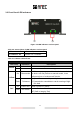
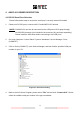
3.2 Front Panel LED Indicators
Table 3-2-1 Description of LED indicators on front panel
1. Power
Indicator of power status
2. Channel 1 & 2
Channel 1 & 2 indicator
Table 3-2-2 Power LED Indicator
POWER LED INDICATOR
LED Color
Indication
Description
Green
On
Normal
Device in normal operation
Flash
Initialization
System initialization and checking
Yellow
On
Silent mode
MMSI is not yet programmed into the device, such that
the device can not perform as transmit mode, it can
perform only as a “receive mode” device.
Flash
TX timeout
(1) Quiet time command imposed by harbor authorities;
(2) Transmission ceased due to carrier-sensing of high
VDL load
Red
On
Power error
Power system is in failure
Flash
BIIT alarm
An abnormal condition of the device is detected during
BIIT (Built In Integrity Test)
Figure 3-2 LED indicators on front panel
2
3