CAMINO-108S AIS Class B with Integrated Splitter USER MANUAL
COPYRIGHT The entire contents of this instruction manual, including any future updates, revisions, and modifications, shall remain the property of AMEC at all times. Unauthorized copies or reproduction of this manual, either in part or whole, in any form of print and electronic media, is prohibited. The contents herein can only be used for the intended purpose of this manual. DISCLAIMER AMEC is devoted to publish and maintain this product manual.
WARNING! WARNING: The transponder must be installed and configured in conformity with the provided instructions in the manual by qualified installer in order to ensure the device performance. WARNING: It is the responsibility of the operator to handle the AIS device with care. The device cannot replace human vigilance. Therefore it is important to keep a diligent outlook at all times.
TABLE OF CONTENT SYSTEM OVERVIEW ........................................................................................................................... 6 1.1 PRODUCT DESCRIPTION ..........................................................................................................6 1.2 EQUIPMENTS IN THE BOX ........................................................................................................8 2 INSTALLATION...........................................................................
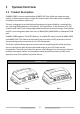
1 System Overview 1.1 Product Description CAMINO-108S is a smart combination of AMEC AIS Class B with our latest antenna splitter. It allows you to share a single VHF antenna with VHF radio, which simplifies installation and reduces cable runs. The unit is designed to provide high performance and great reliability, resulting from our year long field experience. It contains 1 VHF transmitter, 2 AIS receivers on 2 VHF channels and 1 MCU with cutting edge software defined radio technology.
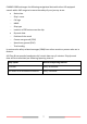
CAMINO-108S exchanges the following navigational data with other AIS equipped vessels within VHF range to increase the safety of your journey at sea: Static data: Ship´s name Call sign MMSI Ship type Location of GPS antenna on the ship Dynamic data: Position of the vessel Course over ground (COG) Speed over ground (SOG) True heading It receives also safety related messages (SRM) from other vessels or persons who are in distress.
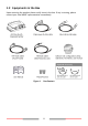
1.2 Equipments in the Box Upon receiving the product please verify items in the box. If any is missing, please contact your local AMEC representative immediately.
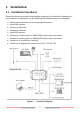
2 Installation 2.1 Installation Procedures Please familiarize the manual content before beginning the installation. Depending on your hardware configuration, use the following recommended steps for installation.
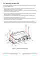
2.2 Mounting the Main Unit The following guidelines should be noticed when selecting the environment to install your AMEC CAMINO-108S: Do not install the device in a flammable or hazardous atmosphere such as in an engine or generator room or close to fuel tanks. Installation of the device should be undertaken in a safe environment without being exposed to any splashing water or rain. There should be adequate space around the device for routing of cables.
2.3 VHF Antenna Installation The quality and positioning of the antenna are the most important factors dictating AIS performance. It is recommended that a VHF antenna with omnidirectional vertical polarization be specifically tuned for marine band. Since the range of VHF signals is largely decided by line of sight distance, the VHF antenna should be placed as high as possible and at least 5 meters away from any constructions made of conductive materials.
2.4 Connecting to VHF Radio Figure 6 VHF Radio Connector It is important for users to make sure that the VHF radio is always connected to the VHF radio input port (left SO-239 connector) – and never connected to antenna input port. When VHF radio is connected to antenna input port, the AIS receiver of CAMINO-108S might be severely damaged. The internal path for VHF radio stays transparent also when CAMINO-108S is switched off or has power failure.
2.5 GPS Antenna Installation Install the GPS antenna where it has a clear view to the sky, so that it may access the horizon freely with 360° degrees. 5˚ Ensure a free 360˚ horizon with a vertical observation of 5˚. Figure 8 3m The recommended horizontal distance between GPS antennas and other antennas is 3m. GPS Antenna Locations It is recommended to keep the GPS antenna out of the transmitting beam of highpower transmitters such as Inmarsat devices and radar.
Base Mounting: 1. Mount the base with the provided screws. 2. Align the GPS cable with the opening slot found on the side of the GPS Antenna. Note: Lightly pull the GPS cable outward to ensure that the cable is not lodged between the GPS Antenna and the pole while is being secured. 3. Align the GPS Antenna to the pole and turn clockwise until is securely tightened. Figure 10 GPS Antenna Base Mounting WARNING: Applicable to Pole and Base mount installations.
2.6 Connecting with NMEA 0183 Devices CAMINO-108S supports two NMEA 0183 ports and external silent mode switch with its 12-pin data cable. The default NMEA 0183 baud rates are 38400-bps (high speed) and 4800-bps (low speed). User can change the baud rates using the provided configuration utility. Typically the high speed setting is primarily for chart plotter connection, while the low speed setting can be used for NMEA 0183 compatible instruments. CAMINO-108S NMEA 0183 supports multiplexer function.
2.7 AIS Silent Mode Connection When Silent Mode is required, it is possible to connect an external toggle switch to CAMINO-108S. Connect the toggle switch between the pink and light green (and/or light blue) wires to enable Silent Mode function, as depicted in Figure 13. An optional external Tx Switch Box (part number SB-181) is available from AMEC for silent mode activation.
2.8 Connection to NMEA 2000 Network The CAMINO-108S is equipped with NMEA 2000 interface with LEN=1. CAMINO-108S is able to send AIS data and forward received GPS data (from internal GPS antenna) via NMEA 2000 network to other NMEA 2000 devices. An updated PGN list is available at AMEC website under FAQ for CAMINO-108. A compatible T-connector and drop cable available by your local service partner are needed to connect the device to your chart plotter with NMEA 2000 interface.
3 Configuring Your CAMINO-108S Your CAMINO-108S is delivered with a powerful “AIS Configuration Tool” allowing user to set up the transponder and make a real-time diagnosis. A more detailed user guide of configuration tool can be found in the “Help” of the software. 3.1 Connecting to your AIS Transponder 3.1.1 Required Items Before preceding the configuration procedure, make sure the following items are available: USB Driver (included in the software CD) USB cable (included in the box) Mac OS X 10.
3.1.3 Three steps to connect AIS transponder Step 1: Connect your Class B AIS transponder to your PC or Mac using a USB cable. In most cases the USB driver will be installed automatically by Windows system. When USB driver installation is not done automatically, it can be found on the attached CD and installed manually. Follow the on-screen instructions and assign the correct file path of the USB driver to complete the installation.
3.1.4 Home page of the application The application is now communicating with your AIS transponder and will display any preconfigured vessel data on the ‘Home’ page depicted as follows.
3.2 Programming your vessel data After the device is successfully connected with the Configuration Tool, click on the “Configuration” tab.
4 GET STARTED 4.1 Start up CAMINO-108S The device starts up whenever the connected power source is ON. It will operate automatically when the device has been properly configured using the Configuration Software and GPS/VHF antenna are properly installed. The device transmits its own ship positions depending on vessel´s moving speed and should receive information of other vessels in the vicinity. The operation status of the device can be observed with the LED lights on the unit.
4.2 LED Indicators Indicator Light Description Power Green, steady The device has been powered up correctly. By USB power, the Power LED does not light showing that the device is in low power mode. Error Red, steady MMSI is not properly programmed Red, flashing A BIIT system error is detected referring to chapter 4.5, or by USB power Rx Green, flashing The device is receiving AIS data. Tx/Silent Orange, flashing The device is acquiring a GPS fix, no AIS transmission during this time period.
4.3 Built-in Integrity Test (BIIT) With BIIT (Built in Integrity Test) function, the CAMINO-108S is constantly monitoring and testing the integrity of the AIS device. Should an abnormal condition be detected within the device, the Error LED will alert with flashing red light.
5 SPECIFICATIONS 5.1 Product Specifications APPLICABLE STANDARDS EN 301 489-1 V2.1.0 / EN 301 489-3 V2.1.0 IEC 60945 Ed. 4:2002 EN 301 489-1 V2.1.0 / EN 301 489-17 V3.1.0 IEC 62287-1 Ed. 3:2017 EN 301 843-1 V2.1.1 / EN 301 843-2 V2.1.1 IEC 61108-1 Ed. 2:2003 EN 300 440 V2.1.0 EN 300 328 V2.1.0 EN 60950-1:2006 + A11:2009 + A1:2010 + EN 62311:2008 A12:2011 + A2:2013 ITU-R .1371-5, 2014 VHF TRANSPONDER 156.025 MHz ~ 162.
SMA (Female) & dedicated cable with Motorola jack Support two NMEA 0183 interfaces NMEA 0183 (RS-422) Default baud rate 38,400 & 4,800bps Configurable and separate Tx/Rx baud rate Standard IEC 61162-1 / IEC 61162-2 sentences RF PERFORMANCE (SPLITTER) Insertion loss, VHF Radio Receive path Typical 0dB Insertion loss, VHF Radio Transmit path Typical 1dB ENVIRONMENTAL Operating Conditions IEC 60945 “protected” category Operating Temperature -15°C ~ 55°C Waterproof IP54 PHYSICAL Width 157 mm (6.
5.
5.
5.
6 TROUBLESHOOTING The transmitting LED (Green color) is not illuminated, why? The transmitting interval of a Class B transponder is 3 minutes if the speed of the vessel is less than 2 knots. If the speed exceeds 2 knots, the transmitting interval will be 30 seconds. For each transmission, the channel indicator will flash once quickly. The green light from the Tx indicator could be missed if not observed carefully. For AIS transmitting, GPS information from GPS antenna is required.
slower than 2 knots. To add to this, if the receiving party is using non-standard dual channel receiver (a single channel receiver), then in perfect conditions, the receiver will get your full static information every 12 minutes and your MMSI and dynamic information every 6 minutes if you are moored. No data is being received by chart plotter, why? Please check that the power supply is connected correctly at CAMINO-108S.
7 ABBREVIATIONS AIS COG CPA CSTDMA DSC ECS ETA GPS IMO MMSI SOG TCPA TDMA TPI UTC VHF VTS Automatic Identification System Course Over Ground Distance to Closest Point of Approach Carrier-Sense Time Division Multiple Access Digital Selective Calling Electronic Chart System Estimated Time of Arrival Global Positioning System International Maritime Organization Maritime Mobile Service Identity Speed Over Ground Time to Closest Point of Approach Time Division Multiple Access Thread per Inch Coordinated Univers
8 FCC INTERFERENCE STATEMENT NOTE: This equipment has been tested and found to comply with the limits for a Class A digital device, pursuant to part 15 of the FCC Rules. These limits are designed to provide reasonable protection against harmful interference when the equipment is operated in a commercial environment.
DECLARATION OF CONFORMITY Hereby, Alltek Marine Electronics Corp. (AMEC) declares that this CAMINO-108S is in compliance with the essential requirements and other relevant provisions of Radio Equipment Directive (RED) 2014/53/EU.
All AMEC products sold or provided hereunder are merely aids to navigation. It is the responsibility of the user to exercise discretion and proper navigational skill independent of any AMEC product. Appendix: How to Determine Serial Port If you PC/laptop does not have available serial port, you may use a RS232-to-USB adapter. To find out the proper serial port for connection use the following instructions.
NOTE: 36
NOTE: 37
NOTE: 38
Alltek Marine Electronics Corporation 14F-2, No. 237, Sec. 1, Datong Rd., Xizhi Dist., New Taipei City, 22161, Taiwan Tel: +886 2 8691 8568 Fax: +886 2 8691 9569 Email: service@alltekmarine.com Website: www.alltekmarine.