
User's Manual

88
A.1.2 Bidirectional Data Ports
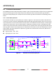
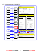
The schematic of bidirectional data port is shown in Figure A2. The schematics inscludes an isoltated full
duplex RS-485 transceiver IC (Texas Instrument ISO3080) which is used as the main component to handle both
data input and output from external data source. The transceiver IC is isolated from external input. To avoid
signal reflection, the transceiver IC has an optional built-in 120Ω loop termination, which is selectable by the
dip-switch on the junction box and the switch should be set to on position when connecting external data
source with long cable. All bidirectional data ports are isolated from one another and are also isolated from
internal power supply. The transceiver internal power supply is fully isolated from the external power supply.
3V3
V5T
3V3
Cable
120
RX_A
TGND
Junction Box
Data
Input
RX_B
TX_B
TX_A
TGND
Data
Output
System Ground
Rx
Tx
To/From
System
Isolated
Isolated Ground
10
10
100K
100K
Main Unit
10K
DE
RX_A
RX_B
TX_B
TX_A
ISO3080
TGND
TGND
TGND
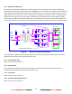
Figure A2 Schematic of bidirectional data port.
The output driver capability of bidirectional data port can provide a maximum of 60mA, and the minimum
differential output swing under 100 Ω load can be 2.3V.
A.1.3 A and B Signal Lines
Refer to sections A.1.1 and A.1.2.
A.1.4 Output Driver
The output driver capability of bi-direction data port can provide maximum 60mA, and the minimum
differential output swing under 100 ohm load can be 2.3V.
A.1.5 Input Load
Refer to sections A.1.1 and A.1.2.
A.1.6 Hardware Input/Output Circuit
Refer to sections A.1.1 and A.1.2.