
User's Manual

103
APPENDIX (B)
B.1 Monitoring of System Functions and Integrity
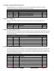
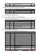
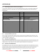
In case a failure is detected in one or more of the following functions or data, an alarm will be triggered and
displayed on the menu-tree under Alarm List, and the system (transponder) will react as described in the
following table.
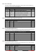
Alarm's description text
Alarm ID
Reaction of the system (transponder)
AIS: Tx malfunction
001
Stop transmission
AIS: Antenna VSWR exceeds limit
002
Continue operation
AIS: Rx channel 1 malfunction
003
Stop transmission on affected channel
AIS: Rx channel 2 malfunction
004
Stop transmission on affected channel
AIS: Rx channel 70 malfunction
005
Continue operation
AIS: general failure
006
Stop transmission
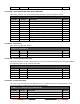
AIS: UTC sync invalid
007
Continue operation using indirect or
semaphore synchronisation
AIS: MKD connection lost
008
Continue operation
AIS: internal / external GNSS position mismatch
009
Continue operation
AIS: NavStatus incorrect
010
Continue operation
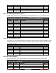
Heading sensor offset
011
Continue operation
AIS: active AIS SART
014
Continue operation
AIS: external EPFS lost
025
Continue operation
AIS: no sensor position in use
026
Continue operation
AIS: no valid SOG information
029
Continue operation using default data
AIS: no valid COG information
030
Continue operation using default data
AIS: Heading lost/invalid
032
Continue operation using default data
AIS: no valid ROT information
035
Continue operation using default data
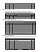
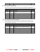
B.2 Antenna VSWR Exceeds Limit
There is a built-in RF output power detector, which is used to monitor the VSWR of VHF antenna port. If the
antenna VSWR exceeds limit, an alarm will be reported while the unit operates continuously. The system will
output an ALR 002 at related PI port.
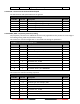
B.3 Detection of Tx Malfunction
A built-in lock detector (high active) is used to monitor the local oscillator (PLL circuit) of the transmitter. If the
operation of PLL circuit becomes abnormal, a logic low (TX malfunction) will be sent from the lock detector to
notify the system. At the same time, system will also output an ALR 001 at the related PI port.
B.4 Detection of Rx Malfunction
The CAMINO-701 also has 3 built-in lock detectors (high active) to monitor each local oscillator (PLL circuit) of
receiver channel 1, channel 2, and channel 70 respectively. If the operation of PLL circuit becomes abnormal, a
logic low level will be sent from the lock detector to notify the system. At the same time, the system will
output ALR 003 or ALR 004 or ALR 005 at the related PI port to indicate the CH1 or CH2 or CH70 RX
malfunctions respectively.