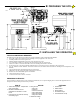
INSTALLATION AND OWNER’S MANUAL Twist’R Plus Class I Vehicular Swing Gate Operator Model RS4000 106502 Serial #: Date Installed: READ THIS MANUAL Your Dealer: New - Allstar’s CGA2K™ TECHNOLOGY! Meets all March 1, 2000 UL325 requirements.
TABLE OF CONTENTS Pre-Installation Notes.......................................... 3 Operator Class Information ............................ 3 Section A: Gate System Design/Installation..... 4 Section B: Preparing the Site ............................ 6 The Concrete Operator Pad............................ 6 Alternate Post Mount ...................................... 6 Placing the Vehicle Detector Loops............... 7 Vehicle Detector Loop Blanking (Shadow).... 8 Electrical Power Requirements ............
PRE-INSTALLATION NOTES The Twist’R Plus (Model RS4000) Vehicular Gate Operator will provide convenience and assurance to the ultimate users for many years. It is ruggedly built of the finest materials and has been thoroughly inspected and tested at the factory. It has many features that will aid in the installation and testing of the complete gate system.
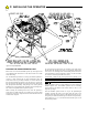
GATE SYSTEM DESIGN / INSTALLATION WARNING! TO REDUCE THE RISK OF SEVERE INJURY OR DEATH: READ AND FOLLOW ALL INSTALLATION INSTRUCTIONS AND GATE SYSTEM DESIGN PARAMETERS! GATE SYSTEM DESIGN AND INSTALLATION SAFETY CHECK LIST: 104949 • The RS4000 operator may be installed on a Class I Vehicular Swing Gate. See page 3 for an explanation of the different Class locations. See the last page of this manual for the operator specifications (voltage, maximum gate weight & length etc.).
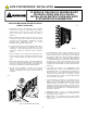
GATE SYSTEM DESIGN / INSTALLATION • SWING GATES HAVE THE POTENTIAL HAZARD OF of the warning signs is a requirement of UL325 and as such failure to install the signs will negate the UL Listing.. If the user refuses to have the warning signs installed, Allstar recommends that you note this on your records and have the user sign a disclaimer. See Figure 4. HANDS AND FINGERS BEING PINCHED between the gate edge and the post to which the gate is mounted.
B: PREPARING THE SITE installation. ALWAYS FOLLOW LOCAL BUILDING CODES. 106505 If no suitable concrete base exists, a pad must be poured. See Figurez6 for plans for this pad. If the location of the operator is such that vehicles have the potential of hitting the operator, consideration should be given to installation of protective posts in front of the operator. If a suitable concrete base already exists for mounting the operator it will be necessary to drill mounting holes for the RS4000 operator.
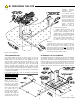
B: PREPARING THE SITE 106508 IN IN OUT OUT Figure 7: Loop Diagrams above grade. Two 13/32 diameter holes will need to be drilled on each side of the 4 x 4 tube. Center each pair of holes on the face of the post 2-5/8” apart and 7/8” down from the top. Each pair of holes is to align with the pre-drilled holes in the chassis mounting angles of the RS4000.
B: PREPARING THE SITE VEHICLE DETECTOR LOOP BLANKING FOR SWING GATES hook up conduit. Low voltage control wires MUST NEVER be routed in the same conduit as the HIGH VOLTAGE power wires. The inside loop for a swing gate installation must be located at least 4 feet outside of the arc of the gate. If it is not, the vehicle detector may detect the gate as it moves over the loop and cause the gate to reopen.
B: PREPARING THE SITE 106504 Figure 8A: Service Conduits C: INSTALLING THE OPERATOR TOOLS and MATERIALS REQUIRED The following tools and materials are required for a proper installation of the Twist'R Plus Model RS4000. 1. Wire cutter, stripper and crimping tools for attaching accessory equipment to the control box. 2. #2 Phillips Head screw driver for general use. 3. Medium standard straight blade screw driver for the terminal strip screws. 4.
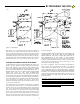
C: INSTALLING THE OPERATOR 106513 Figure 9: Torque Adjustment For previously placed anchor bolts, the procedure is the same except that the bolts will already be in place. If 1/2" diameter anchor bolts were set, the 3/4" mounting holes on the RS4000 pedestal will allow some adjustment for desired alignment. Washers can be used under low corners to accurately level the unit as above.
C: INSTALLING THE OPERATOR Install the gate bracket through the eyelet of the arm end piece and secure it in place with the 1/2-13 x 2” long bolt as shown in Figurez10, using the two flat washers and Nylok nut provided. CAUTION! TO PREVENT DAMAGE TO THE LIMITS, ETC., DURING INSTALLATION OF THE GATE ARM, REMOVE THE LIMIT TRIGGER PIN PRIOR TO INSTALLING THE GATE ARM The RS4000 operator was designed with an Adjustable Torque Output Drive. (“ATD”) (See Figure 9.
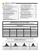
C: INSTALLING THE OPERATOR WARNING! WARNING! TO AVOID ELECTRICAL DAMAGE TO THE OPERATOR DO NOT ALLOW TOTAL WIRE LENGTH FROM THE SERVICE BREAKER PANEL TO THE TWIST’R OPERATOR TO EXCEED THE WIRE LENGTH GIVEN IN TABLEZ1, PAGE 8. RISK OF ELECTROCUTION. DO NOT BEGIN THE ELECTRICAL CONNECTION PROCEDURES UNTIL THE POWER IS TURNED OFF AT THE CIRCUIT BREAKER wiring. See Figure 8. There are cutouts on the bottom of the Operator Chassis to accept these two conduits.
C: INSTALLING THE OPERATOR LIGHTNING PROTECTION RIGHT HAND AND LEFT HAND INSTALLATION For areas where a high probability of ground lightning strikes exists (Florida, Georgia, etc.,) additional lightning protection should be installed in the RS4000. Although it may not be possible to protect against all strikes, additional protection will substantially reduce the occurrence of lightning damage. Allstar’s lightning data indicates that the most strikes enter the RS4000 through the power lines.
C: INSTALLING THE OPERATOR and #3. Connect one of the two wires for the relay to terminal #1 (COMMON) and the other wire to terminal #2 (RADIO RELAY) on the terminal strip. See Figure 16 for connecting 4 wire receivers. ACCESSORY EQUIPMENT HOOK-UP All accessory equipment is connected to the terminal strips located on the control panel of the RS4000. 110473 0 1 2 3 4 5 There are 11 command inputs available to the installer on the RS4000 in addition to 2 commons.
C: INSTALLING THE OPERATOR labeled as COMMON, then connect this to Terminal #1 or #0 of the RS4000 control panel. Connect the other contact to one of the following terminals depending on function desired: Terminal #2 (ALTERNATE), Terminal #4 (RADIO OPEN), Terminal #5 (FREE EXIT), Terminal #6 (OPEN) or Terminal #7 (CLOSE).
D: STARTING THE OPERATOR TERMINAL STRIP REFERENCE CHART # NAME DESCRIPTION 10 CLOSE PHOTO Momentary or continuous signal. This input is active only when referenced to the closing direction, it has no effect on the gate when opening or about to open. If activated when the gate is closing the gate will stop, pause and reverse in the open direction for 1/2 second (approx. 2 inches) and stop. Continuous activation will prevent the gate from moving in the close direction.
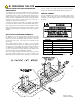
D: STARTING THE Figure 18: Limit Adjustments 106512 mounting hole is positioned directly above the clearance notch provided in the shaft support tower (see Figure 18). This notch provides the appropriate clearance to install the limit trigger pin with the bolt and washers provided. Install the trigger pin firmly in place. belt and the large output pulley, similar to that of a clutch mechanism.
D: STARTING THE OPERATOR TIMER TO CLOSE SETTING RUNNING THE RS4000 The Timer to Close is controlled by the setting of the “AUTO CLOSE TIMER” potentiometer on the control board, see Figure 19. When the pot is adjusted fully counter-clockwise the Timer-To-Close is disabled. Turning the pot approximately 1/4 turn clockwise will enable the Timer To Close function with a delay of approximately 2 seconds between the gate reaching the full open position and automatically closing.
D: STARTING THE MAXIMUM RUN TIMER FINAL SETTING OF THE CLOSE TIMER SMART™ Self adjusting MAximum Run Timer (Patent Pending) To alter the amount of time that the Close Timer will hold the gate open, adjust the timer potentiometer located on the control board. See Figure 19. The RS4000 has a Self adjusting MAximum Run Timer, SMART™ (patent pending). The amount of time for the first few cycles of operation are registered and averaged within the motor controller circuitry.
F: END USER INSTRUCTIONS GATE OPENER OPERATION AND SAFETY To minimize the risk of entrapment in your gate system, have the following safety enhancement features installed where appropriate: To the Owner/End User of Allstar’s Twist'R: Thank you for choosing an Allstar product. We are confident you will have many years of use and satisfaction with your gate operator.
F: END USER INSTRUCTIONS GATE OPENER OPERATION AND SAFETY GUIDE AVOID ENTRAPMENT: Stay away from the path of the gate MAINTAIN THE GATE AND GATE HARDWARE: A and all moving parts (gate arms, etc.) at all times. Keep clear of the damaged gate or one that cannot be easily opened and closed pinch points identified below.. Install guards or other safety enhancement manually must be repaired before installing a gate operator. A poorly features to prevent access to pinch point areas.
TWIST’R EXPLODED VIEW 110508 Figure 24: Twist’R Operator Exploded View 22
TWIST’R PARTS LIST ITEM QTY. PART # ITEM DESCRIPTION QTY. PART # DESCRIPTION 1 1 EA 103918 REDUCER, SPEED, 60:1 16 1 EA 104482 CAPACITOR BRACKET 1a 1 EA 110674 BRACKET, REDUCER SUPPORT, LEFT 17 1 EA 005120 CAPACITOR 1b 1 EA 110673 BRACKET, REDUCER SUPPORT, RIGHT 18 1 EA 110507 BACKPANEL ASSEMBLY, CGA2K NS NLA 103994 BRACKET, REDUCER, U, ONE PIECE 19 2 EA 105550 SNAP RING 2 1 EA 103911 PULLEY, POLY VEE, 2.2 P.D. 20 2 EA 105525 WASHER 3 1 EA 104050 PULLEY,3L,2.5 P.D. X .
TECHNICAL SPECIFICATIONS DRIVE PHYSICAL DRIVE SYSTEM: 60:1 Via V-Belt, Motor Drive, Gear PAD: 16” x 24” x 3” Elevation or 4 x 4 Post OVERHEAD CLEARANCE: Minimum 12” FINAL SPEED: 3.3 RPM UNIT SIZE: 19”W x 14-1/2”L x 11”H OUTPUT SHAFT: 1” Diameter from bottom of chassis COVER: One-Piece Molded Polyethylene with no LIMITS: Independent Open/Close; Radial Swing Switches SHIPPING WEIGHT: 51 lbs. CAPACITIES ELECTRICAL MAX. GATE WEIGHT: 300 lbs. PRIMARY VOLTAGE: 115 VAC, 60 Hz, 1P MAX.