WDS2454AP 802.
Regulatory notes and statements Wireless LAN, Health and Authorisation for use Radio frequency electromagnetic energy is emitted from Wireless LAN devices. The energy levels of these emissions however are far less than the electromagnetic energy emissions from wireless devices like mobile phones. Wireless LAN devices are safe for use as defined by the relevant frequency safety standards and recommendations.
4. Consult the dealer or an experienced radio/TV technician for help. Safety Information Your device contains a low power transmitter. When device is transmitted it sends out radio frequency (RF) signal. CAUTION: To maintain compliance with FCC’s RF exposure guidelines, this equipment should be installed and operated with a minimum distance of 20cm between the Antenna and your body. Unauthorized antenna, modification, or attachments could damage the transmitter and may violate FCC regulations.
TABLE OF CONTENTS About This Guide ................................................................................................................................................. 1 Purpose .............................................................................................................................................................. 1 Overview of this User’s Guide ........................................................................................................................
ABOUT THIS GUIDE Congratulations on purchasing the WDS2454AP Wireless Access Point. This manual contains detailed instructions o n the operation of this product. Please keep this manual for future reference. With the WDS2454AP Wireless Access Point, wireless enabled devices can share data with each other and with wired LAN devices. The WDS2454AP supports both client and Bridging applications.
UNPACKING AND SETUP This chapter provides unpacking and setup information for the Access Point. Unpacking Open the box of the Access Point and carefully unpack it. The box should contain the following items: u u u u One Wireless Access Point One external power adapter One CD-Rom (User’s guide) 2x Antennas (WDS2454AP-A5 only) If any item is found missing or damaged, please contact your local reseller for replacement.
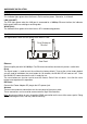
HARDWARE INSTALATION LED Indicator PWR/Power This indicator lights green when the Access Point receives power. Otherwise, it will be off. LAN (Link/ACT) The LED lights green when the LAN port is connected to a 100Mbps Ethernet station, the indicator blinks green while transmitting or receiving data . WLAN (Link) The indicator blinks green while the wireless AP is broadcasting packets.
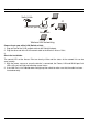
Hardware connections Notebook Switch/Hub P S O W ER YST EM N LA 1 2 3 Lin k/A 0 1 M 0 4 C PC T Ethernet port Notebook Wireless LAN Networking Connecting to your office LAN (Switch or Hub) 1. Plug one end of the RJ45 network cable to the Switch/Hub port, 2. Plug the other end of the RJ45 network cable to the Wireless Access Point. 3. Check the installation The control LEDs of the Access Point are clearly visible and the status of the network link can be seen instantly: 1.
CONFIGURING THE WIRELESS LAN ACCESS POINT The Wireless Access Point has an easy to use Web GUI interface for configuration. The AP can be configured through a Web Browser. A network manager can manage, control and monitor the AP from the local LAN. This section indicates how to configure the AP. Login to the Wireless AP through WLAN Before configuring the Wireless AP through a wireless client, make sure that the SSID, Channel and the WEP key have been configured correctly.
If you have configured a username and password for the access point you will be prompted with a login box when you enter the IP address in to the web browser. Enter the appropriate username and password and hit enter. Note: by default there is no username and password set in to the device.
Main Screen of the Access Point The first screen that appears in the browser is the station summary page. There are six main functions included on the left side of the main screen: Network, Security, Status, Clients, Tools and Configuration.
Network The Network Section is used to configure the IP address of the unit, Wireless settings and the WDS Links of the Access Point. I. LAN Setup The LAN Setup function is used to configure the basic LAN settings: Dynamic (DHCP Client): Select Dynamic for dynamic IP address allocation from a DHCP Server. Static IP: Select Static to configure an IP Address, Subnet Mask and Gateway for the Access Point. II. Wireless Settings The wireless settings screen contains two sections Radio Settings and Wireless LAN.
Wireless LAN Settings: to configure the wireless network settings. Ø Wireless Network Name (SSID): SSID is an ASCII string up to 32 characters that is used to identify the WLAN and prevents the unintentional merging of two co-located WLANs. The SSID value must be the same in all stations and AP’s in the extended WLAN. Ø Band: you can select to change the radio band to mixed mode, G-only or B-only, a window will pop up to change the policy. Mixed mode: Supports both 802.11g and 802.11b clients.
III. WDS Links WDS (Wireless Distribution System) uses wireless bridging to communicate with other APs. When you enter the WDS screen a list of available AP’s will appear. To create a WDS link with a particular Access Point click enable on the left side of the screen and click apply to add the AP to your WDS Link, or click the “Add WDS Link” button to add the APs that you need to add. The WDS Link will scan and find all available access points running within a range of 3 channels.
Security The WDS2454AP provides a range of security features used to prevent unauthorised access to your wireless network. These security features include, WPA, 802.1x and WEP. If a particular security feature has been enabled a tick box or a number will be displayed next to the corresponding security feature. Ø Check sign means that the function is enabled. Ø The numbers show how many Radius servers have been configured. I.
II. Radius Server A RADIUS server is used to authenticate the connection for clients and return authentication key parameters to the users to connect to the wireless network. RADIUS (Remote Authentication Dial-In User Service) utilises a RADIUS server for authentication and the use of dynamic TKIP, AES, or WEP. Re-authentication Time: Enter a time in seconds that uses will have to re-authenticate with the RADIUS server.
III. Wired Equivalent Privacy (WEP) WEP encryption implementation was not put in place with the 802.11 standard. This means that there are about as many methods of WEP encryption as there are providers of wireless networking products. In addition, WEP is not completely secure. One piece of information still not encrypted is the MAC address, which hackers can use to break into a network by spoofing (or faking) the MAC address.
Ø Use WPA with Pre-Shared Key: type in 8 ~ 63 characters inside the dialog box to setup the WPA password used between the AP and the clients. Ø Use WPA with Radius Server: the authe ntication between the Radius Server, the AP and the clients using the Group Key Re-key Settings. No Rekeying: the clients will not need to re-key the password to authenticate with the Radius Server. Rekeying Time: Type in the time in minutes when clients will need to re-key the password for authentication and security.
II. Wireless Statistics This screen shows the statistics of the wireless AP.
III. Event Report This screen shows all events that have occurred on the AP, press “Reset Event Log” to clear the record of the events.
Clients This function shows the list of the wireless clients connected to the AP. I. Wireless Clients This function shows the list of wireless clients that are connected to the AP. II. Access Points This function shows the list of Wireless Access Points that the AP can connect to, this is the list that you can use for WDS Links, refer for the WDS Links on page 10.
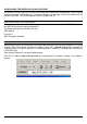
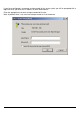
Tools This function will help you to upgrade the firmware of the AP, press the “Upgrade Firmware” button in the left side of the menu screen and a window will appear as shown below. Press “Next “. Type the firmware file that you need to upgrade inside the dialog box, or press the “Browse” button to find the firmware file location. Press the “Upgrade” button to proceed with the upgrade procedure.
When uploading the file to the AP, do not power off the AP until the “Firmware Upgrade Complete” screen appears. Press the “Reset” button on the rear panel of the AP, to reset to unit back to factory default.
Configuration I. Change Password This function will help you to configure the password of the AP, type in the new password inside the New password and Confirm password dialog box, press the “Change password” button to activate this function. II. Lock Access Point Lock the Access Point to deny configuration changes to it. You need to have physical access to the Access Point to unlock it, press the reset button on the rear panel of the AP to unlock.
TECHNICAL SPECIFICATIONS General Standards Standard: IEEE 802.11g IEEE 802.3 u 10/100BASE-TX Fast Ethernet Signal Type: OFDM (Orthogonal Frequency Division Multiplexing) Modulation: QPSK / BPSK / CCK / OFDM LED Indicators: Power, LAN (Link/Activity), WLAN (Link) Frequency Range 2412 ~ 2484 MHz ISM band (channels 1 ~ 14) Frequency Band: 2.