Wireless LAN 802.11g Series WLF-2454AP-S User’s Guide Version 1.0 Alloy Wireless 802.11g User’s Guide www.alloy.com.
Contents 1. Introduction ............................................................................................................... 2 2. Safety Notification .................................................................................................... 3 3. Hardware Installation................................................................................................ 4 4 Web Management Settings ....................................................................................... 5 4.1.
1. Introduction Thank you for purchasing the WLF2454AP-S Wireless 802.11g AP Router. This user guide will assist you with the installation procedure. The package you have received should contain the following items: AP Router Wireless 802.11g AP Router Power Supply / Cord Ethernet Cable Installation CD Note: if anything is missing, please contact your dealer. Alloy Wireless 802.11g User’s Guide www.alloy.com.
2. Safety Notification Your Wireless AP Router should be placed in a safe and secure location. To ensure proper operation, please keep the unit away from water and other damaging elements. Please read the user manual thoroughly before you install the device. The device should only be repaired by authorized and qualified personnel. Please do not try to open or repair the device yourself. Do not place the device in a damp or humid location, i.e. a bathroom.
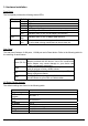
3. Hardware Installation Front Panel The front panel provides the following status LED’s. LED STATUS Description PWR/STAT Off No power Red On 1. Power on Red Blink 1. System startup LAN Off no Ethernet link detected Green On 10/100Mbps Fast Ethernet link detected. No activity.
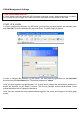
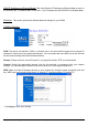
4 Web Management Settings TURN ON POWER SUPPLY A ‘Quick’ power cycle can cause the AP’s firmware to become corrupt. When powered on, be careful not to power the unit off again for at least 5 seconds, while data is being written to the flash. START UP & LOGIN In order to configure the Wireless 11g AP Router, you must use your web browser and manually enter http://192.168.1.1 into the Address box and press Enter. The Main Page will appear.
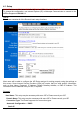
4.1. Setup ENSURE YOU HAVE THE CORRECT NETWORK SETTINGS IN YOUR COMPUTER To change the configuration, use Internet Explorer (IE) or Netscape Communicator to connect to the WEB management 192.168.1.1. Setup This screen contains all of the Router's basic setup functions. . Most users will be able to configure the AP Router and get it working properly using the settings on this screen.
PPPoE (Point-to-Point Protocol over Ethernet) PPTP (Point-to-Point Tunneling Protocol) These options can be selected from the drop-down menu next to Internet Connection. The information required and available features will differ depending on what kind of connection type you select. Descriptions of these options: Internet IP Address and Subnet Mask (Static IP or PPTP) This is the Router's IP Address and Subnet Mask as seen by external users on the Internet (including your ISP).
LAN IP Address and Subnet Mask: This is the Router's IP Address and Subnet Mask as seen on the internal LAN. The default value is 192.168.1.1 for IP Address and 255.255.255.0 for Subnet Mask. Wireless: This section provide the Wireless Network settings for your WLAN 2.4GHz Settings SSID: The service set identifier ( SSID ) or network name. It is case sensitive and must not exceed 32 characters, which may be any keyboard character.
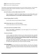
4.2. Security Router Password: Changing the password for the AP Router is as easy as typing the password into the Enter New Password field. Then, type it again into the Re-enter to confirm. * Click the Apply button to save the setting. Use the default password when you first open the configuration pages, after you have configured these settings, you should set a new password for the Router (using the Security screen). This will increase security, protecting the Router from unauthorised changes.
Web Filters: Using the Web Filters feature, you may enable up to four different filters. • Proxy - Use of WAN proxy servers may compromise network security. Denying Proxy will disable access to any WAN proxy servers. To enable proxy filtering, click the box next to Proxy. • Java - Java is a programming language for websites. If you deny Java, you run the risk of not having access to Internet sites created using this programming language. To enable Java filtering, click the box next to Java.
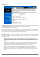
4.3. System Restore Factory Defaults: Click the Yes button to reset all configuration settings to factory default values. Note: Any settings you have saved will be lost when the default settings are restored. Click the No button to disable the Restore Factory Defaults feature. Click the Apply button to save the setting. Firmware Upgrade: Click the Upgrade button to load new firmware onto the Router.
4. On the Firmware Upgrade screen, click the Browse button to find the firmware upgrade file. 5. Double-click the firmware upgrade file. 6. Click the Upgrade button, and follow the on-screen instructions. Note: Do not power off the Router or press the Reset button while the firmware is being upgraded. Multicast Pass-Through: IP Multicasting occurs when a single data packet is sent to multiple recipients at the same time.
To clone your network adapter’s MAC address onto the Router and avoid calling your ISP to change the registered MAC address, follow these instructions. 1. Select Enable. 2. Enter your adapter's MAC address in the MAC Address field. 3. Click the Apply button. To disable MAC address cloning, keep the default setting, Disable. Remote Management: This feature allows you to manage your Router from a remote location, via the Internet. To disable this feature, keep the default setting, Disable.
4.4. DHCP The DHCP screen allows you to configure the settings for the Router's Dynamic Host Configuration Protocol (DHCP) server function. The Router can be used as a DHCP server for your network. A DHCP server automatically assigns an IP address to each computer on your network. If you choose to enable the Router's DHCP server option, you must configure your entire network of PCs to connect to a DHCP server, the Router.
WINS: The Windows Internet Naming Service (WINS) manages each PC’s interaction with the Internet. If you use a WINS server, enter that server’s IP Address here. Otherwise, leave this blank. Currently Assigned: Click the DHCP Clients Table button to see a list of PCs assigned IP addresses by the Router. For each PC, the list shows the client hostname, MAC address, IP address, and the amount of DHCP client lease time left. Click the Refresh button to display the most current information.
4.5. SNMP SNMP: The SNMP screen allows you to customize the Simple Network Management Protocol (SNMP) settings. SNMP is a popular network monitoring and management protocol. To enable the SNMP support feature, select Enable. Otherwise, select Disable. SNMPv2c Identification SNMP Community Contact In the contact field, enter contact information for the Router. Device Name In the Device Name field, enter the name of the Router.
4.6. Status This screen displays the Wireless Router's current status and settings. This information is read-only. This page will auto re-fresh every 5 seconds to keep the most up to date information. Host Name: The Host Name is the name of the Router. This entry is necessary for some ISPs. Domain Name: The Domain Name is the name of the Router's domain. This entry is necessary for some ISPs. DHCP Release: Click the DHCP Release button to delete the Router's current Internet IP address.
4.7. Advanced Wireless Wireless MAC Filters: This function allows the administrator to have access control by entering MAC addresses of client stations. When this function has been Enabled, two new options will appear. Depending on the filtering purpose, it can be selected to Prevent or Permit access. Click on Edit MAC Filter List to add the client stations to the MAC list. The table can store up to 40 different MAC addresses. Please follow the format that is required when an address is to be entered.
Authentication Type: Auto: Auto is the default authentication algorithm. The AP will change its authentication type automatically to fulfill client’s requirement. Open System: Open System authentication is not required to be successful while a client may decline to authenticate with any particular other client. Shared Key: Shared Key is only available if the WEP option is implemented.
Fragmentation Threshold: This value specifies the maximum size for a packet before data is fragmented into multiple packets. It should remain at its default setting of 2346. If you experience a high packet error rate, you may slightly increase the Fragmentation Threshold. Setting the Fragmentation Threshold too low may result in poor network performance. Only minor modifications of this value are recommended. AP Mode or Wireless Bridge Mode: The WLF2454AP-S can operate in two modes.
4.8. Filters The Internet Filter screen allows you to block or allow specific kinds of Internet usage. You can set up Internet access policies for specific PCs and set up filters by using network port numbers. This feature allows you to customize up to 10 different Internet Access Policies for particular PCs, which are identified by their IP or MAC addresses.
Note: This screen's settings will vary depending on which Policy Type you select . 4. Select Deny or Allow, depending on how you want to control access for specific PCs. 5. Click the Edit List button next to PCs or Internet PCs. a. On the List of PCs or List of Internet PCs screen, specify PCs by IP address or MAC address. Enter the appropriate IP addresses into the IP fields. If you have a range of IP addresses to filter, complete the appropriate IP Range fields.
4.9. Port Forwarding The Port Forwarding screen sets up public services on your network, such as web servers, ftp servers, e-mail servers, or other specialized Internet applications. (Specialized Internet applications are any applications that use Internet access to perform functions such as videoconferencing or online gaming. Some Internet applications may not require any forwarding.
Customized Applications External Port Enter the name of the public service or other Internet application in the field provided. TCP Protocol UDP Protocol IP Address Enable Click this checkbox if the application requires TCP. Click this checkbox if the application requires UDP. Enter the IP Address of the PC running the application. Click the Enable checkbox to enable port forwarding for the application.
4.10. Routing On the Routing screen, you can set the routing mode and settings of the Router. Gateway mode is recommended for most users. The default setting is Gateway. Operating Mode Choose the correct working mode. Keep the default setting, Gateway, if the Router is hosting your network's connection to the Internet (Gateway mode is recommended for most users). Select Router if the Router exists on a network with other routers. Note: This feature is not available in Gateway mode.
the Router and the network or host. 3. Depending on where the Destination IP Address is located, select LAN & Wireless or Internet (WAN) from the Interface drop-down menu. 4. To save your changes, click the Apply button. To cancel your unsaved changes, click the Cancel button. For additional static routes, repeat steps 1-4. To delete a static route entry: 1. From the Static Routing drop-down list, select the entry number of the static route. Delete This Entry 2. Click the Delete This Entry button. 3.
4.11. DDNS The Router offers a Dynamic Domain Name System (DDNS) feature. DDNS lets you assign a fixed host and domain name to a dynamic Internet IP address. It is useful when you are hosting your own website, FTP server, or other server behind the Router. Before using this feature, you need to sign up for DDNS service with one of two DDNS service providers, DynDNS.org or TZO. DynDNS.org To disable DDNS Service, keep the default setting, Disable. To enable DDNS Service using DynDNS.
5. Troubleshooting Basic Functions Note: If you are using a cable or DSL modem and are experiencing problems connecting to the Internet, follow these steps: 1. Power off your cable or DSL modem, PC, and the Router. 2. Power on your modem and wait a few minutes until the modem has established a connection with your ISP. 3. Power on the Router. 4. Power on your PC and attempt to connect to the Internet. For most users, the Router's default values should be satisfactory.
Resolution: Make sure that each computer has a unique IP Address. If using DHCP through the AP Router, make sure that each computer is enabled to use the DHCP function and restart the computer. Make sure that the Link LED is on. If it is not, try a different network cable. Check each computer for correct network settings. Wireless Troubleshooting I can’t access the Wireless AP Router from a wireless network card Cause: Out of range. IP Address is not set correctly.