GSS Series User Manual User Manual GSS Series 16/24 Port Gigabit Web Managed Switch (GSS-16T4SFP & GSS-24T4SFP) Version 1.0 Sep.
GSS Series User Manual Table of Contents CAUTION ..............................................................................................................................................3 ELECTRONIC EMISSION NOTICES ..........................................................................................................3 ABOUT THIS USER MANUAL .................................................................................................................4 OVERVIEW OF THE USER MANUAL ................
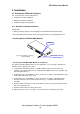
GSS Series User Manual Caution Electronic Circuit devices are sensitive to static electricity. Dry weather conditions or walking across a carpeted floor may cause you to acquire a static electric charge. To protect your switch, always: • Touch the metal chassis of your computer to ground the static electrical charge before you handle the switch. • Pick up the switch by holding it on the left and right edges only.
GSS Series User Manual About this User Manual This User Manual will guide you on procedures to install, configure and monitor Alloy 16 port Gigabit (GSS-16T4SFP) and 24 port (GSS-24T4SFP) Gigabit web Managed Switch models utilizing the built-in web management interface. The two models GSS-16T4SFP and GSS-24T4SFP differ in terms of port density – the former model offering 16x 10/100/1000Mbps Gigabit Ethernet ports, and the latter 24x ports of the same specification.
GSS Series User Manual 1. Introduction 1.1 Overview Alloy 16/24 Port Gigabit Switches meet all IEEE 802.3/u/x/z standards Gigabit and Fast Ethernet specifications. The 16 Port Gigabit Switch model features 16x 10/100/1000Mbps copper RJ-45 ports and 4x Gigabit Ethernet SFP Ports.
GSS Series User Manual 1.2 Key Features • • • • • • • 16 or 24 10/100/1000Mbps Gigabit Ethernet Ports all compliant with IEEE802.3, 802.3u, 802.3z and 802.3ab 4 Paired TP/SFP fibre ports Web Based Management Port Based VLAN and Tag-based (IEEE802.1q) VLAN 802.1p Class of Service with 2 level priority queuing Port Trunking with flexible load distribution and failover function Port mirroring function 1.
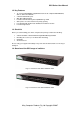
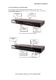
GSS Series User Manual 1.4.1 User interfaces on the front panel The front panel of the GSS-16T4SFP and GSS-24T4SFP consists of 16x or 24x 10/100/1000Mbps Copper Gigabit Ethernet ports, 4x SFP fibre ports and 1x reset button to restore factory configuration. LED Display Panel Gigabit Ethernet Ports Factory Default Button SFP Fibre Ports Fig. 1.3 Front Panel of the GSS-16T4SFP LED Display Panel Gigabit Ethernet Ports Factory Default Button SFP Fibre Ports Fig. 1.
GSS Series User Manual LED Indicators LED COLOUR Power System LED’s Lit when Power is active Gigabit Copper Ports Green Lit when link is active, flashes when traffic is present Green/Amber Lit green when 1000Mb link Lit amber when 100Mb link Off when 10Mb link or no link present Gigabit Fibre Ports Green Lit when link is active, flashes when traffic present Green Link/Act 10/100/1000Mbps SFP(LINK/ACT) FUNCTION Note: All SFP ports are paired with one of the 10/100/1000Mbps copper RJ-45 ports.
GSS Series User Manual 1.5. Overview of the Optional SFP Modules With the GSS-16T4SFP switch, the SFP ports are paired with RJ-45 copper ports 13, 14, 15 and 16. In the case of the GSS-24T4SFP, the SFP ports are paired with RJ-45 copper ports 21, 22, 23 and 24. Only one of any given paired port can be used. In this manner, these paired ports can be seen as ‘Dual Media’ ports that support 10/100/1000Mbps or 1000Mbps fibre via the SFP interfaces.
GSS Series User Manual 2. Installation 2.1. Starting the GSS Series Switches This section provides a quick start guide for: • Hardware and Cable Installation • Management Station Installation • Software booting and configuration 2.1.1.
GSS Series User Manual • Copper Ports - Cable Installation Please Note: ⇒ The RJ-45 ports on the GSS Series Gigabit Switches support MDI/MDI-X autocrossover functionality. This enables use of either straight-through or crossover UTP cable types; the RJ-45 ports will automatically be configured to suit the characteristics of the device at the remote end of the link.
GSS Series User Manual 2.1.2. Cabling Requirements To help ensure a successful installation and keep network performance at optimum levels, take care to use Cat.5E grade or higher cabling. Ensure that stranded core UTP cable, if used, runs for no more than 10 metres, and that solid core runs for a maximum of 100metres. Poor cabling is the most common cause for network dropouts or poor performance. 2.1.2.1.
GSS Series User Manual Cont. Please Note: ⇒ Further information can be found in section 1.5 on page 7 ⇒ All figures denoting the range a given cable type can achieve must be treated as maximum values.
GSS Series User Manual 3. Operation of the Web Based Management The following chapter allows the administrator to monitor and manage the GSS series through the web management interface. Management functionality such as Port Based and 802.1q VLAN, Port Aggregation (Trunking), QoS, Port configuration and much more can all be configured quickly and easily via any port of the GSS series switches.
GSS Series User Manual 3.1 Web Management Home Overview Once you have entered a valid password and logged into the switch the System Configuration page will be displayed, this is the default page, it will be displayed every time that you log into the switch. On the left hand side of the screen you will see a menu structure used to Configure, Monitor and manage your switch. There are three main menu categories Configuration, Monitoring and Maintenance.
GSS Series User Manual 3.2 Configuration 3.2.1 System Information The System Information configuration page is used to display basic switch information including the Model Name, MAC Address, Firmware Version, Hardware Version, IP and SNMP information. Fig. 3.2 System Desc: Displays a brief description of the switch. (Read Only) F/W Version: Displays the current firmware loaded into the switch. (Read Only) H/W Version: Displays the current hardware version.
GSS Series User Manual Management VLAN: Enter the VLAN group used to gain access to the web management. Default value is 1. If you change this value only ports belonging to the VLAN group chosen can manage the switch. Password: If you want to change the default password of the switch please enter it here. Default password is admin. Inactivity Timeout: Used to automatically log you out of the management interface after a specified inactivity time. Time is measured in Seconds, Default value is 0.
GSS Series User Manual 3.2.2 Ports The ports configuration page is used to display the current status of each port on the switch. In this section the user can also change the speed settings and flow control of each port and Jumbo Frame support can also be enabled from this location. Fig. 3.3 Enable Jumbo Frames: Tick the check box to enable Jumbo Frame support on each port. Port: Is the physical port number of the switch. Link Status: Displays the current link status of each port.
GSS Series User Manual Drop Frames after Excessive Collisions: Used when running half duplex equipment, tick the check box to enable this feature. Apply Button: The Apply button must be pressed after making any changes to any of the values on this screen. Refresh Button: Used to refresh the current settings displayed on the screen.
GSS Series User Manual 3.2.3 VLAN Mode The GSS Series of switches support port based VLAN’s, 802.1q tagged VLAN’s and Metro mode VLAN’s. Up to 16 active Port Based VLAN groups can be configured with a PVID from 1 ~ 4094 for the GSS-16T4SFP and 24 active Port Based VLAN groups can be configured for the GSS-24T4SFP. 24 802.1q Tagged based VLAN’s can be created on both models with a PVID ranging from 1 ~ 4094. Fig. 3.4 VLAN Mode: Select which VLAN mode you would like to use.
GSS Series User Manual Metro-Mode: Metro Mode VLAN’s is a quick method of creating 13, 14, 15 or 16 port based VLAN groups. Each port is separated into its own VLAN group with 1, 2, 3, or 4 ports belonging to each group. Each group contains its own port and the uplink port. Double Tag: Double Tag also known as Q in Q is used to encapsulate a second VLAN tag inside an Ethernet packet. This type of scenario is mainly used for service provider networks.
GSS Series User Manual 3.2.4 VLAN Group Tag Based VLAN’s Fig. 3.5 VLAN ID: To create a new VLAN group, Enter a valid VLAN ID into the space provided. A new screen will appear as shown below: Fig. 3.6 Description: Enter a Descriptive name for the VLAN. Ports: Select what ports you want to be members of this VLAN and tick there corresponding check boxes. Select All: Used to automatically select all ports. Refresh Button: Used to refresh the current settings displayed on the screen.
GSS Series User Manual Apply Button: The Apply button must be pressed after making any changes to any of the values on this screen. Port Config: Used to configure per port parameters. Fig. 3.7 Port: Is the physical port number of the switch. Ingress Filtering Enabled: Tick the check box to enable Ingress Filtering. Packet Type: Select each port to accept All types of packets including tagged and untagged packets, or only allow each port to accept Tagged packets.
GSS Series User Manual Fig. 3.8 Modify: Select the radio button next to the VLAN you wish to modify and click modify. Delete: Select the radio button next to the VLAN you wish to delete and click delete. Refresh Button: Used to refresh the current settings displayed on the screen.
GSS Series User Manual Port Based VLAN’s Fig. 3.9 VLAN ID: To create a new VLAN group, Enter a valid VLAN ID into the space provided. A new screen will appear as shown below: Fig. 3.10 Description: Enter a Descriptive name for the VLAN. Ports: Select what ports you want to be members of this VLAN and tick there corresponding check boxes. Select All: Used to automatically select all ports. Refresh Button: Used to refresh the current settings displayed on the screen.
GSS Series User Manual Apply Button: The Apply button must be pressed after making any changes to any of the values on this screen. Fig. 3.11 Modify: Select the radio button next to the VLAN you wish to modify and click modify. Delete: Select the radio button next to the VLAN you wish to delete and click delete. Refresh Button: Used to refresh the current settings displayed on the screen.
GSS Series User Manual Metro Mode VLAN’s Fig. 3.12 Uplink Port: Select the port(s) that you wish to use as your uplink port(s). This is the port(s) that belongs to each individual VLAN. Apply Button: The Apply button must be pressed after making any changes to any of the values on this screen. Fig. 3.12 Modify: Select the radio button next to the VLAN you wish to modify and click modify. Delete: Select the radio button next to the VLAN you wish to delete and click delete.
GSS Series User Manual 3.2.5 Aggregation Port Aggregation is used to Aggregate Ports into a logical trunk usually called Link Aggregation. Link Aggregation can bundle more than one port with the same speed, full duplex and the same MAC address to be a single logical port, thus the logical port aggregates the bandwidth of these ports. This allows the switch to aggregate multiple ports together to form a high bandwidth backbone link. Fig 3.
GSS Series User Manual 3.2.6 LACP Link Aggregation Control Protocol is a protocol used to dynamically trunk ports into groups that have the same LACP key value. Fig 3.14 Port: The physical ports of the switch. Protocol Enabled: Tick the checkbox to enable LACP on the particular port. Apply Button: The Apply button must be pressed after making any changes to any of the values on this screen. Refresh Button: Used to refresh the current settings displayed on the screen.
GSS Series User Manual 3.2.7 RSTP The Spanning Tree Protocol is an IEEE 802.1d standard designed for avoiding unwanted loops in switched networks. When STP/RSTP is enabled only a single path will be active between any two nodes on a network. Spanning Tree is also used as a redundancy method to eliminate down time if a device or cable goes down on your network.
GSS Series User Manual Protocol Enabled: Used to enable the Rapid Spanning Tree Protocol on individual ports. Edge: Edge will be enabled if the port is connecting to an end device such as a workstation. Edge will be disabled if connecting to another STP aware device. Path Cost: A value set to each port to allow the switch to determine which port will be a forwarding port. The lowest path cost value will be used as the forwarding port.
GSS Series User Manual 3.2.8 802.1x The 802.1x port-based network access control provides a method to restrict users to access network resources via authenticating user’s information. This restricts users from gaining access to the network resources through an 802.1x-enabled port without authentication. Any user wishing to access the network through a port under 802.
GSS Series User Manual Action: Re-authenticate forces the port to re-authenticate with the RADIUS server. Force Re-initialise forces the port to re-initialise with the RADIUS server. Statistics displays the 802.1x statistics of each individual port. Fig. 3.16 Refresh Button: Used to refresh the current settings displayed on the screen.
GSS Series User Manual 802.1x Parameters Fig. 3.18 Re-authentication Enabled: Tick the checkbox to force re-authentication between the port and the RADIUS after a pre-determined time interval. Re-authentication Period: Used to set the time before re-authentication occurs. Time interval can be set between 1 and 3600 seconds. EAP Timeout: Used to set the timeout value of the EAP authentication. Time interval can be set between 1 and 255 seconds.
GSS Series User Manual 3.2.9 IGMP IGMP Snooping is used to establish multicast groups to forward multicast packets to each of the multicast member ports, and, in nature, avoids wasting bandwidth with IP multicast packets. If a switch does not support IGMP or IGMP Snooping it can not tell a multicast packet from a broadcast packet, so it will treat them all as broadcast packets.
GSS Series User Manual 3.2.10 Port Mirroring The Mirror function of the GSS Series is used to capture data from a particular port on the switch. Any port on the switch can be selected as the monitoring port; this port will be used to capture data from another port on the switch using third party data capturing software. Data can be captured from more than one port on the switch simultaneously therefore you can have one monitoring port and several other ports being monitored by the one port. Fig. 3.
GSS Series User Manual 3.2.11 Quality of Service Two methods of Quality of Service is available in the GSS Series, they are 802.1p QoS – Is a tag based QoS method normally used with 802.1q VLAN’s. Inside each Ethernet packet 3 bits are reserved for QoS purposes, priority levels are then set based on the value of the 3 bit field inside the packet. The GSS Series can then set High, Medium, Normal and Low priorities based on the 3 bit value.
GSS Series User Manual 3.2.11.2 Quality of Service – DSCP Fig. 3.22 QoS Mode: Used to set the required QoS method. Options are 802.1p and DSCP. Prioritise Traffic: Used to set the priority of each 3 bit value. Priority values range from 0 through to 7. A high, Medium, Normal or Low class can be applied to each 3 bit priority value. Port Number: Select the desired port to configure. DSCP Value (0 – 63): Used to apply a particular priority class to a certain DSCP value.
GSS Series User Manual 3.2.12 Filter The filtering function of the GSS Series is used to block unwanted devices from accessing the switch. The filtering rules are based on an IP Address, both static and dynamic IP addressing can be used. Fig. 3.23 Port: Is the physical port number of the switch. Mode: Used to disable or enable the filtering function. Either static or dynamic IP addressing can be selected here. IP Address: If using a static IP address, enter the IP address here.
GSS Series User Manual 3.2.13 Rate Limit The Rate Limit function of the GSS Series is used to limit the speed of each port on the switch. Fig. 3.24 Traffic Rate Unit: Is used to select the incremental value of the rate limit. You can set a rate limit based on 128K, 512K, 1M, 10M or 32M. If you select 128K you can then select a rate value for each port. If the rate value is set to 1, the port will be limited to 128K. If the rate limit is set to 2 then the port will be limited to 256K.
GSS Series User Manual 3.2.14 Storm Control Storm Control is used to limit the amount of Broadcast, Multicast and Unicast frames allowed to enter the switch. These limits are based on the amount of frames allowed to be received per second. Fig. 3.25 ICMP Rate: Used to set the number of frames allowed to be received by the switch per second. The preset values are: 1K, 2K, 4K, 8K, 16K, 32K, 64K, 128K, 256K, 512K, 1024K or No Limit.
GSS Series User Manual 3.2.15 SNMP Fig. 3.26 SNMP Enabled: Used to enable or disable SNMP. SNMP Trap Destination: Enter the IP address of a device used to receive SNMP Traps. SNMP Get Community: Enter the SNMP Get community name in the space provided. SNMP Set Community: Enter the SNMP Set community name in the space provided. SNMP Trap Community: Enter the SNMP Trap community name in the space provided. Cold Boot: Tick this check box for an SNMP trap to be sent when the event occurs.
GSS Series User Manual 3.3 Monitoring 3.3.1 Detailed Statistics The detailed port statistics screen shows you in detail statistics of each individual port. Fig. 3.27 Check Boxes: Tick the check boxes next to each of the statistics that you wish to monitor. Apply Button: The Apply button must be pressed after making any changes to any of the values on this screen. Refresh Button: Used to refresh the current settings displayed on the screen.
GSS Series User Manual 3.3.2 LACP Status Displays the status of all LACP based port aggregation groups. Fig. 3.28 Refresh Button: Used to refresh the current settings displayed on the screen.
GSS Series User Manual 3.3.3 RSTP Status Displays the current status of RSTP. Fig. 3.29 Refresh Button: Used to refresh the current settings displayed on the screen.
GSS Series User Manual 3.3.4 IGMP Status Displays the current status of multicast groups learnt by the switch. Fig. 3.30 Refresh Button: Used to refresh the current settings displayed on the screen.
GSS Series User Manual 3.3.5 Ping The ping function of the switch is used to test communication between other IP enabled devices on your network. Fig. 3.31 Target IP Address: Enter the IP address of an IP device on your network in which you want to test communication with. Count: Select the number of times you would like to ping the device. Available options are 1, 5, 10 and 20. Time Out: Enter the time out value from the drop down box provided. Available options are 1, 5, 10 and 30.
GSS Series User Manual 3.4 Maintenance 3.4.1 Warm Restart Fig. 3.32 Click Yes to reboot the device or No to cancel the operation.
GSS Series User Manual 3.4.2 Factory Default Fig. 3.33 Click Yes to restore the factory default settings on the switch, or No to cancel the operation.
GSS Series User Manual 3.4.3 Software Upgrade Fig. 3.34 Browse: Used to select the firmware file to load into the switch. Upload: Once the file has been located, press the upload button to upgrade the switches firmware. Cancel: Press cancel to cancel the operation.
GSS Series User Manual 3.4.4 Configuration File Transfer The GSS Series allows the user to backup and restore the configuration settings of the switch. Fig. 3.35 Configuration Download Download: Used to download the current configuration of the switch. Once pressed a dialog box will appear asking you where you would like the file saved. Configuration Upload Browse: Click the browse button to search for the backed up configuration file of the switch.
GSS Series User Manual 3.4.5 Logout Press the logout button to logout of the web management.
GSS Series User Manual Appendix A – Technical Specifications Hardware Specifications Standard Compliance: IEEE802.3/802.3ab / 802.3z / 802.3u / 802.
GSS Series User Manual Diagnostic LED: System LED : Per Port LED: 10/100/1000M TP Port 1 to 12 10/100/1000M TP Port 1 to 20 1000M SFP Fibre Port 13~16 1000M SFP Fibre Port 21~24 Power Requirement : Power : LINK/ACT, 10/100/1000Mbps : LINK/ACT, 10/100/1000Mbps : SFP(LINK/ACT) : SFP(LINK/ACT) AC Line Voltage : 100∼240 V Frequency : 50∼60 Hz Consumption : 30W Ambient Temperature : 0° to 50°C : 5% to 90% Humidity Dimensions : 44(H) × 442(W) × 209(D) mm Comply with FCC Part 15 Class A, C-Tick