POE100 Series 10/100 Base-TX to 100Base-FX Converter POE Power Provider Version 1.
1. Overview The POE Series IEEE 802.3u compliant media converters support two types of media 10/100 Base-TX and 100Base-FX. With LFP (Link Fault Propagation) support it allows the administrator to easily diagnose link faults on their network. If the Copper or Fibre link fails, the converter forces the link status of the connecting device to also fail.
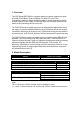
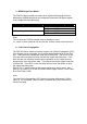
. Checklist Before you start installing the POE converter, please verify that the package contains the following items. - The POE100 Series AC Power Cord CD containing this manual Please notify your sales representative if any of the above items are missing or damaged. 4. Installing the Converter 4.1 POE100 converter with a Powered Device (PD) 1. Connect the POE100 converter to an AC power source. 2. Connect the copper cable to your IEEE 802.3af compliant PD device. e.g.
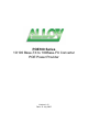
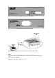
Fig. 1 View of the POE100 Series Media Converter Fig. 2 Example connection between POE100, PD device and Fibre Cable 100FX Fibre Network RX TX TX RX POE100 Series Media Converter AC VOIP PoE Phone, (PoE PD) or PoE Splitter Fig.
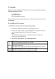
10/100Base-TX to 100Base-FX Converter PO E100 Series PO E Po wer Provid er Fig. 4 POE100 Series Media Converter Front Panel Fig. 5 POE100 Series Media Converter Rear Panel Fig. 6 Pairs used for transmitting power over Ethernet Cable. Note: The pins used for delivering power to the Powered Device follow the IEEE 802.3af standard.
5. WDM Single Fibre Model The POE100 Series media converter has an optional Wavelength Division Multiplexing (WDM) Model that can transport bi-directional full duplex signals over a single fibre simultaneously. Single Fibre Model 1310nm Single Mode 20Km 1550nm Single Mode 20Km TX, RX Wavelength TX (Transmit) 1310nm RX (Receive) 1550nm TX (Transmit) 1550nm RX (Receive) 1310nm Note: The 1310nm and 1550nm models must be installed in pairs, i.e.
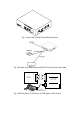
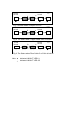
10/100 Switch TP LFP ● ● ● B C A LFP Fibre Cable 10/100 Switch Remote Station TP ● ● ● Fig. 7 Normal Status via a pair of LFP’s 10/100 10/100 Switch Switch A B LFP LFP TP TP C Fibre Cable ● ○ ○ ○ ○ ○ ● Remote Station ● Fig. 8 The Status when Copper Cable A link is broken 10/100 Switch LFP TP ○ B LFP C Fibre Cable ○ ○ ○ ○ 10/100 A Switch Remote Station TP ○ ● Fig.
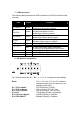
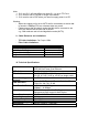
7. LED Description The following table describes the LED’s located on the POE100 Series media converter. LED Colour FX LNK/ACT Green FX FDX/COL Amber TP LNK/ACT Green TP 100 Green PWR Green Green PoE PSE-TP 4W 7W 15.
Note: 1. S1-2 and S1-3 will take effect only when S1-1 is set to TP-Force 2. S1-5 must be set to 100FDX for Single Fibre Model 3. S1-6 must be set to POE when you need to supply power to a PD. Warning: - When the copper port is set to AUTO and is connected to a device that is forced to 100Mbps FDX, an unknown state may result. - Please ensure that all network nodes that this device connects to are set to the same mode at each end of the link. e.g., Both ends are set to Auto-Negotiation mode (AUTO) 9.