INSTALLATION MANUAL KAP 140 FLIGHT CONTROL SYSTEM MANUAL NUMBER 006--00991--0006 REVISION 6 OCT, 2002
WARNING Prior the export of this document, review for export license requirement is needed. COPYRIGHT NOTICE . 1998, 2002 Honeywell International Inc. Reproduction of this publication or any portion thereof by any means without the express written permission of Honeywell is prohibited. For further information contact the Manager, Technical Publications, Honeywell, One Technology Center, 23500 West 105th Street Olathe KS 66061 Telephone: (913) 782--0400.
BENDIX/KING KAP 140 REVISION HISTORY REV DATE CHANGES 4 August, 1998 Add unit versions 5 March, 2002 Add unit versions --2603, --5403, --7703 6 October, 2002 Add unit versions --2704, --5504, --7904 CS:00991I06.
BENDIX/KING KAP 140 RH--2
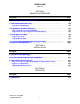
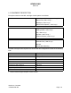
BENDIX/KING KAP 140 SECTION I GENERAL INFORMATION Paragraph Page 1.1 KAP 140 FLIGHT CONTROL SYSTEMS . . . . . . . . . . . . . . . . . . . . . . . . . . . . . . . . . 1 -- 1 1.2 EQUIPMENT DESCRIPTION . . . . . . . . . . . . . . . . . . . . . . . . . . . . . . . . . . . . . . . . . . . 1.2.1 Modes of Operation . . . . . . . . . . . . . . . . . . . . . . . . . . . . . . . . . . . . . . . . . . . . . . . 1 -- 2 1 -- 4 1.3 TECHNICAL CHARACTERISTICS . . . . . . . . . . . . . . . . . . . . . . . . . . . . .
BENDIX/KING KAP 140 LIST OF ILLUSTRATIONS Figure 2 -- 1 2 -- 2 2 -- 3 2 -- 4 2 -- 5 2 -- 6 2 -- 7 Page KC 140 OUTLINE AND INSTALLATION DWG . . . . . . . . . . . . . . . . . . . . . . . . . KS 270C, KS271C & KS 272C WITH KM 275 INSTALLATION DWG . . . . . KS 270C, KS 271C, KS 272C WITH KM 277 INSTALLATION DWG . . . . . . . KCM 100 INSTALLATION DWG . . . . . . . . . . . . . . . . . . . . . . . . . . . . . . . . . . . . . . KC 140 INTERCONNECT . . . . . . . . . . . . . . . . . . . . . . . . . . . . . . . . .
BENDIX/KING KAP 140 SECTION I GENERAL INFORMATION 1.1 KAP 140 FLIGHT CONTROL SYSTEMS The KAP 140 Flight Control System was developed in 1996 to provide up to two axis digital flight control to the entry level General Aviation market. This system is designed with several options for customer flexibility. The KAP140 is offered as a single--axis (roll) and as a two--axis (pitch and roll) system. Manual Electric Trim can be added to any system. Autotrim can be added to a two--axis system.
BENDIX/KING KAP 140 1.
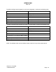
BENDIX/KING KAP 140 The KAP 140 Flight Control System for a two axis configuration consists of the following units: UNIT DESCRIPTION KC 140 Flight Computer KCM 100 Configuration Module KS 270C Pitch Axis Servo Actuator KS 271C Roll Axis Servo Actuator Supplied by Mid--Continent Rate Gyro Supplied by SIGMA--TEK DG KM 275 or KM 277 (Total of 2 Required) Servo Mount The KAP 140 Flight Control System for a single axis configuration consists of the following units: UNIT DESCRIPTION KC 140 Fli
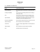
BENDIX/KING KAP 140 1.2.1 MODES OF OPERATION MODE FUNCTION PROVIDED Vertical Speed(VS) Pitch default mode to hold and track vertical speed reference. Heading Select(HDG) Roll command to the heading selected on the heading indicator (DG or HSI). NAV Roll command to capture and track a navigation course provided by a NAV, GPS, or Localizer (w/o GS tracking). Approach(APR) Roll and Pitch commands to capture and track LOC and GS Beams, VOR and GPS Approach course.
BENDIX/KING KAP 140 1.3 TECHNICAL CHARACTERISTICS 1.3.1 System Technical Characteristics (In smooth air) Maximum Bank Angles Limited to standard rate turn.
BENDIX/KING KAP 140 1.3.2 System Components Technical Characteristics KC 140 TSO Compliance: See Appendix A Physical Dimensions (Nominal): Width: Height: Length: Including Rack & Mating Connector 6.306 in (16.02 cm) 1.665 in (4.229 cm) 11.35 in (28.829 cm) + 1.71 (4.343 cm) (--7XXX) 11.35 in (28.829 cm) + .75 (1.91 cm) (--2XXX, --5XXX) (--2XXX) 2.5 lbs. (1.1 kg) (--5XXX) 2.6 lbs. (1.2 kg) (--7XXX) 2.6 lbs. (1.
BENDIX/KING KAP 140 Glideslope Valid: NAV Valid: >180mV for Valid >180mV for Valid Middle Marker Sense: 1 Wire, 3VDC Minimum for MKR on Pitch Trim Servo Voltage: 2 Wire, DC Differential voltage Trim Sense: 2 Wire, DC Differential voltage DG Valid: Open = Invalid, Ground = Valid Pitch Servo Drive: 2 Wire DC Differential, --10 to +10 VDC max. 2 Wire DC Differential, --10 to +10 VDC max. 2 Wire DC Differential, --10 to +10 VDC max.
BENDIX/KING KAP 140 KS 270/1/2 C TSO Compliance: Physical Dimensions(Nominal): Length: See Appendix A Height: Width: 4.605 in (11.70 cm) without KM275 or KM277 4.675 in (11.87 cm) 3.925 in (9.97 cm) Weight: (Nominal) KS 270C: KS 271C: KS 272C: KM 275 Servo Mount KM 277 Servo Mount 2.5 lbs (1.09 kg) 2.2 lbs (1.00 kg) 2.1 lbs (0.95 kg) 1.0lbs (.45 Kg) “ “ Mounting: Two (2) AN 3 bolts Mating Connector: 030--03248--0000 Power Inputs: +28VDC at 4.
BENDIX/KING KAP 140 1.4 UNIT INSTALLATION 1.4.1 Unit Flavors 1.4.1.
BENDIX/KING KAP 140 1.4.1.3 KM 275 The KM 275 is available in the following versions: Part Number Slip Clutch Used 065--0030--00 200--01678--0000 (Standard) 065--0030--02 200--02380--0000 1.4.1.4 KM 277 Preset Torque (in--lbs) Variable Variable The KM 277 is available in the following versions: Part Number 065--0041--00 1.4.1.
BENDIX/KING KAP 140 1.4.2.
BENDIX/KING KAP 140 1.4.2.4 KCM 100 Configuration Module Installation Kit The KCM 100 Installation Kit (PN 050--03245--0000) consists of the following items: SYMBOL CAS PART NBR DESCRIPTION [UOM] --0000 _ 030--01157--0011 SOCKET CRMP 20G [EA] 10 _ 030--02351--0005 HOOD/LVR ASSY SD E [EA] 1 P 1010 030--01171--0000 CONN SUB--D HSG 9S [EA] 1 1.4.2.5 KM 277 Servo Mount Installation Kit The KM 277 does not require an installation kit. Revision 6, Oct 2002 CS:00991I06.
BENDIX/KING KAP 140 1.4.3 Certification Diskettes Installation of the KAP 140 Automatic Flight Control System requires the use of a certification diskette. This certification diskette contains files that define certain parameters that are uploaded to the KCM 100 configuration module and then used by the KC 140. These files are aircraft specific and each aircraft certification will have three separate files.
BENDIX/KING KAP 140 1.5 ACCESSORIES REQUIRED BUT NOT SUPPLIED Some of the following accessories are required, but not supplied as a part of the KAP 140 Flight Control System. Consult the appropriate STC data for requirements pertaining to your aircraft. A. KI 525A (PN 066--3046--XX) Horizontal Situation Indicator and installation kit (PN 050--01344--XXXX). B. KA 51B (PN 071--1242--XX) Compass Slaving Accessory and installation kit (PN 050--01928--XXXX). C.
BENDIX/KING KAP 140 SECTION II INSTALLATION 2.1 GENERAL INFORMATION This section contains general suggestions and information to consider before installation of the KAP 140 Flight Control System. Close adherence to these suggestions will assure optimum performance from the equipment. Specific installation requirements are contained in the STC Installation Manual that pertains to the particular type of aircraft which the equipment is to be installed.
BENDIX/KING KAP 140 2.3.2 KC 140 Installation The KC 140 installation will conform to standards designated by the customer, installing agency, and existing conditions as to the unit location and type of installation. However, the following instructions will assure a more satisfactory performance from the equipment. Mounting locations are provided near the front and rear of the mounting rack. It is necessary to utilize both the front and rear mounting locations when installing the KC140 mounting rack.
BENDIX/KING KAP 140 2.3.3.1.2 RTI Menu Operation The main menu provides selection of entering diagnostic mode, displaying the error log, displaying the Software Identification number, or configuring the installation. The following sections provide specific instructions on using these capabilities to perform the required installation and ground checkout procedures. NOTE: Selection of diagnostics will inhibit normal operation of the flight computer. Revision 6, Oct 2002 CS:00991I06.
BENDIX/KING KAP 140 2.3.3.1.3 Configuration Procedure 1. To configure/install the flight computer, the following must be completed: AFCS system harness installation checked (ring test). Aircraft ground power applied. Avionics power applied. Sensors operating (Turn Coordinator, DG/HSI, nav’s). RS232 communications established with FCC.
BENDIX/KING KAP 140 A “1” for “Remote Baro” will cause the system to use the baro set input from the altimeter and disable the ability to change baro set from the FCC (although it will still display baro set when the BARO button is pressed). A “1” for “HSI/DG” will select the proper operation for a system with an HSI. A “0” is the proper selection for a DG installation. A “1” for “Trim Installed” will configure the system to provide Manual Electric Trim.
BENDIX/KING KAP 140 NOTE For the roll and pitch axis null adjustments, adjust the pot until 0 + .020 volts DC is measured across the servo drive pins D and L of the roll servo and the pitch servo harness connectors. This is accomplished as follows: First, allow the FCC to pass pre--flight test; then unplug the servo connector from the aircraft harness. Next apply an aircraft ground to pin K of the harness connector.
BENDIX/KING KAP 140 In a two--axis installation, create a valid Glideslope signal and null the deviation display. Now select the GS Deviation and press “ENTER”. This will compensate for any offsets in the glideslope tracking. This completes the installation offset adjustments. Now return to the top--level menu by pressing “ENTER” twice, to prevent accidental changes in the offset parameters. 2.3.3.2.
BENDIX/KING KAP 140 press the UP switch without pressing ARM and check for no trim response. Do the same with the DN switch. NOTE: An active UP or DN switch without ARM will trip a latent switch failure monitor after three seconds. For SW MOD 01/05 software or later, “PT” will be annunciated on the KC 140 and MET operation will be disabled until all three MET switch inputs are inactive.
BENDIX/KING KAP 140 Revision 6, Oct 2002 CS:00991I06.
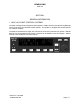
BENDIX/KING KAP 140 FACE VIEW INPUT=> OUTPUT=< TABLE 2--1 KC 140 CONNECTOR J1401 PIN FUNCTIONS Pin I/O Description 1 < ROLL CLUTCH 2 > HDG DATUM + 3 > ROLL RATE -- 4 < CFG_+5V 5 > ROLL SERVO VALID 6 < AUDIO ALERT 7 > ILS 8 <> CFG DATA 9 > AP DISCONNECT 10 > RATE VALID 11 > DG VALID 12 > DIM BUS 13 < CFG ENABLE 14 > AUDIO POWER 15 > CHASSIS GROUND 16 > AIRCRAFT POWER 17 > STRAP 5 18 < ROLL SERVO CMD 19 < ROLL SERVO CMD REF 20 < TONE ALERT 21 >
BENDIX/KING KAP 140 Pin I/O Description 26 > CWS 27 > CRS/HDG DATUM REF 28 < TXD RS232 29 30 31 > < > RXD RS232 CFG CLK STRAP 1 32 > STRAP 2 33 > STRAP 3 34 > STRAP 4 35 > GROUND 36 > STRAP 6 37 < VISUAL ALERT Revision 6, Oct 2002 CS:00991I06.
BENDIX/KING KAP 140 FACE VIEW INPUT=> OUTPUT=< TABLE 2--2 KC 140 CONNECTOR J1402 PIN FUNCTIONS Pins I/O Description 1 < TRIM CLUTCH 2 > TRIM VOLTAGE -- 3 > C2 4 > TRIM VOLTAGE -- 5 > C4 6 > TRIM SENSE + 7 < PITCH SERVO CMD 8 < PITCH CLUTCH 9 > GS + UP 10 > GS + DN 11 > A1 12 > GS -- FLAG 13 > A2 14 > A4 15 > CHASSIS GROUND 16 > BARO SET 17 > CRS DATUM + 18 < DG +15 VDC 19 < DG --15 VDC 20 > B4 21 > C1 22 > TRIM UP Revision 6, Oct 2002 CS
BENDIX/KING KAP 140 Pins I/O Description 23 > TRIM SENSE 24 < PITCH SERVO CMD REF 25 > TRIM ARM 26 > GPS SELECT 27 > TRIM DOWN 28 > PITCH SERVO VALID 29 > D4 30 > STALL WARNING 31 > GS + FLAG 32 < TRIM SERVO CMD 33 > B1 34 > B2 35 > XPNDR REF 36 < TRIM SERVO CMD REF 37 < BARO REF SUPPLY 38 > MIDDLE MARKER 39 SPARE 40 > ROLL STEER VALID *** 41 > ROLL STEER + *** 42 > ROLL STEER -- *** 43 > PFT CONTROL EN 44 < TRIM FAIL ANN 45 > FLAPS +
BENDIX/KING KAP 140 P270C1 A TACH +* B VALID TP C POWER GND D COMMAND REF E AP DISCONNECT F CLUTCH LOW H +28V J TRIM SENSE + K VALID BAR L COMMAND M VALID TP N CHASSIS GROUND P VREF (REFERENCE VOLTAGE), TACH --* R TRIM SENSE -- *For --2X00 servos only TABLE 2--3 KS 270C CONNECTOR PIN FUNCTIONS Revision 6, Oct 2002 CS:00991I06.
BENDIX/KING KAP 140 P271C1 A TACH TEST B VALID TP C POWER GND D COMMAND REF E AP DISCONNECT F CLUTCH LOW H +28V J SPARE K VALID BAR L COMMAND M VALID TP N CHASSIS GROUND P VREF (REFERENCE VOLTAGE) R SPARE TABLE 2--4 KS 271C CONNECTOR PIN FUNCTIONS Revision 6, Oct 2002 CS:00991I06.
BENDIX/KING KAP 140 TOP VERSION # CLUTCH LOW CONNECTION (PIN LETTER) 065 -- 00180 -- 0400 B 065 -- 00180 -- 0600 K 065 -- 00180 -- 1400 P 065 -- 00180 -- 2700 F 065 -- 00180 -- 3500 M TABLE 2 -- 5 CLUTCH LOW KEYING *P272C1 * SEE TABLE 2 -- 5 FOR CLUTCH LOW KEYING PER UNIT VERSION NUMBER A DISABLE BAR B SEE TABLE 1 C POWER GND D COMMAND REF E AP DISCONNECT F SEE TABLE 1 H +28V J MOTOR FEEDBACK 1 K SEE TABLE 1 L COMMAND M SEE TABLE 1 N CHASSIS GROUND P SEE TABLE 1 R MOT
BENDIX/KING KAP 140 FACE VIEW INPUT=> OUTPUT=< Pin I/O Description 1 > + 5VDC IN 2 <> GROUND 3 > CFG ENABLE 4 > CFG CLOCK 5 <> CFG DATA 6 SPARE 7 SPARE 8 SPARE 9 SPARE TABLE 2--7 KCM 100 CONNECTOR J1010 PIN FUNCTIONS Revision 6, Oct 2002 CS:00991I06.
BENDIX/KING KAP 140 BLANK PAGE MARKER (NEW) Revision 6, Oct 2002 CS:00991I06.
BENDIX/KING KAP 140 FIGURE 2--1 KC 140 OUTLINE AND INSTALLATION DRAWING (Dwg No 155--06027--0001, Rev 4) (Sheet 1 of 1) Revision 6, Oct 2002 CS:00991I06.
BENDIX/KING KAP 140 BLANK PAGE MARKER (NEW) Revision 6, Oct 2002 CS:00991I06.
BENDIX/KING KAP 140 FIGURE 2--2 KS 270C, KS271C & KS 272C WITH KM 275 INSTALLATION DRAWING (Dwg No 155--05161--0000, Rev AC) (Sheet 1 of 1) Revision 6, Oct 2002 CS:00991I06.
BENDIX/KING KAP 140 BLANK PAGE MARKER (NEW) Revision 6, Oct 2002 CS:00991I06.
BENDIX/KING KAP 140 FIGURE 2--3 KS 270C, KS 271C, KS 272C WITH KM 277 INSTALLATION DRAWING (Dwg No 155--05241--0000, Rev AA) (Sheet 1 of 1) Revision 6, Oct 2002 CS:00991I06.
BENDIX/KING KAP 140 BLANK PAGE MARKER (NEW) Revision 6, Oct 2002 CS:00991I06.
BENDIX/KING KAP 140 FIGURE 2--4 KCM 100 INSTALLATION DRAWING (Dwg No 155--06008--0000, Rev 1) (Sheet 1 of 1) Revision 6, Oct 2002 CS:00991I06.
BENDIX/KING KAP 140 BLANK PAGE MARKER (NEW) Revision 6, Oct 2002 CS:00991I06.
BENDIX/KING KAP 140 FIGURE 2--5 KC 140 INTERCONNECT (Dwg No 155--01679--0000, Rev AC, Sheet 1 of 5) Revision 6, Oct 2002 CS:00991I06.
BENDIX/KING KAP 140 BLANK PAGE MARKER (NEW) Revision 6, Oct 2002 CS:00991I06.
BENDIX/KING KAP 140 FIGURE 2--5 KC 140 INTERCONNECT (Sheet 2 of 5) Revision 6, Oct 2002 CS:00991I06.
BENDIX/KING KAP 140 BLANK PAGE MARKER (NEW) Revision 6, Oct 2002 CS:00991I06.
BENDIX/KING KAP 140 FIGURE 2--5 KC 140 INTERCONNECT (Sheet 3 of 5) Revision 6, Oct 2002 CS:00991I06.
BENDIX/KING KAP 140 BLANK PAGE MARKER (NEW) Revision 6, Oct 2002 CS:00991I06.
BENDIX/KING KAP 140 FIGURE 2--5 KC 140 INTERCONNECT (Sheet 4 of 5) Revision 6, Oct 2002 CS:00991I06.
BENDIX/KING KAP 140 BLANK PAGE MARKER (NEW) Revision 6, Oct 2002 CS:00991I06.
BENDIX/KING KAP 140 FIGURE 2--5 KC 140 INTERCONNECT (Sheet 5 of 5) Revision 6, Oct 2002 CS:00991I06.
BENDIX/KING KAP 140 BLANK PAGE MARKER (NEW) Revision 6, Oct 2002 CS:00991I06.
BENDIX/KING KAP 140 FIGURE 2--6 KC140 COMPUTER CABLE ASSEMBLY (Dwg No 155--02794--0000/0002, Rev 1) (Sheet 1 of 1) Revision 6, Oct 2002 CS:00991I06.
BENDIX/KING KAP 140 BLANK PAGE MARKER (NEW) Revision 6, Oct 2002 CS:00991I06.
BENDIX/KING KAP 140 FIGURE 2--7 CLUTCH ADJUSTMENT (Dwg No 159--08155--5006, Rev 1) (Sheet 1 of 5) Revision 6, Oct 2002 CS:00991I06.
BENDIX/KING KAP 140 BLANK PAGE MARKER (NEW) Revision 6, Oct 2002 CS:00991I06.
BENDIX/KING KAP 140 FIGURE 2--7 CLUTCH ADJUSTMENT (Dwg No 159--08155--5006, Rev 1) (Sheet 2 of 5) Revision 6, Oct 2002 CS:00991I06.
BENDIX/KING KAP 140 BLANK PAGE MARKER (NEW) Revision 6, Oct 2002 CS:00991I06.
BENDIX/KING KAP 140 FIGURE 2--7 CLUTCH ADJUSTMENT (Dwg No 159--08155--5006, Rev IR) (Sheet 3 of 5) Revision 6, Oct 2002 CS:00991I06.
BENDIX/KING KAP 140 BLANK PAGE MARKER (NEW) Revision 6, Oct 2002 CS:00991I06.
BENDIX/KING KAP 140 FIGURE 2--7 CLUTCH ADJUSTMENT (Dwg No 159--08155--5006, Rev 1) (Sheet 4 of 5) Revision 6, Oct 2002 CS:00991I06.
BENDIX/KING KAP 140 BLANK PAGE MARKER (NEW) Revision 6, Oct 2002 CS:00991I06.
BENDIX/KING KAP 140 FIGURE 2--7 CLUTCH ADJUSTMENT (Dwg No 159--08155--5006, Rev IR) (Sheet 5 of 5) Revision 6, Oct 2002 CS:00991I06.
BENDIX/KING KAP 140 BLANK PAGE MARKER (NEW) Revision 6, Oct 2002 CS:00991I06.
BENDIX/KING KAP 140 SECTION 3.0 OPERATION 3.1 GENERAL Refer to the STC installation manual of the particular aircraft which the system is installed for operating procedures or the Flight Manual Supplement of the particular aircraft. Revision 6, Oct 2002 CS:00991I06.
BENDIX/KING KAP 140 Revision 6, Oct 2002 CS:00991I06.
BENDIX/KING KAP 140 TSO APPENDIX RTCA DO--160C ENVIRONMENTAL QUALIFICATION FORMS Revision 6, Oct 2002 CS:00991I06.
BENDIX/KING KAP 140 BLANK PAGE MARKER (NEW) Revision 6, Oct 2002 CS:00991I06.
BENDIX/KING KAP 140 Revision 6, Oct 2002 CS:00991I06.
BENDIX/KING KAP 140 Revision 6, Oct 2002 CS:00991I06.
BENDIX/KING KAP 140 Revision 6, Oct 2002 CS:00991I06.
BENDIX/KING KAP 140 Revision 6, Oct 2002 CS:00991I06.
BENDIX/KING KAP 140 Revision 6, Oct 2002 CS:00991I06.
BENDIX/KING KAP 140 Revision 6, Oct 2002 CS:00991I06.
BENDIX/KING KAP 140 Revision 6, Oct 2002 CS:00991I06.
BENDIX/KING KAP 140 Revision 6, Oct 2002 CS:00991I06.
BENDIX/KING KAP 140 Revision 6, Oct 2002 CS:00991I06.
BENDIX/KING KAP 140 Revision 6, Oct 2002 CS:00991I06.
BENDIX/KING KAP 140 Revision 6, Oct 2002 CS:00991I06.
BENDIX/KING KAP 140 Revision 6, Oct 2002 CS:00991I06.
BENDIX/KING KAP 140 Revision 6, Oct 2002 CS:00991I06.
BENDIX/KING KAP 140 Revision 6, Oct 2002 CS:00991I06.
BENDIX/KING KAP 140 Revision 6, Oct 2002 CS:00991I06.
BENDIX/KING KAP 140 Revision 6, Oct 2002 CS:00991I06.
BENDIX/KING KAP 140 Revision 6, Oct 2002 CS:00991I06.
BENDIX/KING KAP 140 Revision 6, Oct 2002 CS:00991I06.
BENDIX/KING KAP 140 Revision 6, Oct 2002 CS:00991I06.
BENDIX/KING KAP 140 Revision 6, Oct 2002 CS:00991I06.
THE END