
Specifications


GS660 Technical Manual Page 25
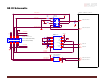
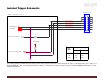
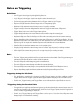
Isolated Trigger Schematic
USER POWER
CABLE SIDE
ISOLATED GROUND
SYNC INPUT 1 (DRIVER)
4.7K
5V
USER
POWER
0
1.8K
R2
POWER GROUND
SYNC INPUT 1
RECOMMENDED VALUES
3M 10114-3000PE
1
2
3
4
5
6
7
8
9
10
11
12
13
14
SYNC OUTPUT 1 (RECEIVER)
2.7K
SYNC OUTPUT 1
POWER GROUND
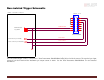
USERS TRIGGER CIRCUIT
R2
12V 0.7K
12V POWER
R1
R1
12V_POWER
24V
1K
This circuit assumes a 10mA drive current (I
F
) from User’s trigger circuit into camera through R1. R2 is connected to the open collector of
Fairchild MOCD207. The corresponding transistor emitter is connected to isolated ground. See the Fairchild MOCD207 datasheet for more
detailed information.