
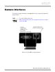
Instruction manual

C
C
ame
r
r
a I/O
The Ge
n
on the
with s
h
conn
Pin
S
1
E
P
2
E
3
C
4
I
5
C
6
V
7
R
8
E
P
9
E
10
T
11
R
12
C
13
C
14
N
G
n
eral Purpo
s
camera side
h
ielded hous
i
Th
i
A
V
ector
S
igna
l
E
xternal
P
ower
E
xternal GND
C
amera In 1
I
solated GND
C
amera Out1
V
ideo Iris
R
eserved
E
xternal
P
ower
E
xternal GND
T
xD RS232
R
xD RS232
C
amera In 2
C
amera Out 2
N
on-isolated
G
ND
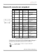
Table 8:
P
s
e I/O port u
s
. The matin
g
i
ng 3M 1031
i
s cable side
V
T P/N: 02-7
0
pin a
s
Direction
---
---
In
---
Out
Out
---
---
---
Out
In
In
Out
---
P
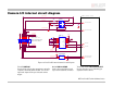
rosilica GS I
/
s
es a 3M 10
2
g
cable conn
4-3210-00X
Hirose con
n
0
03A
AVT Pr
o
s
sign
m
Leve
l
+5 V…+12
(see note)
GND for po
U
in
(
high
)
=
5 V...24 V
U
in
(low) =
0 V...0.8 V
---
Open emit
t
max. 20m
A
---
---
+5 V…+16
(see note)
GND for ex
t
power
RS232
RS232
LVTTL
max. 3.3 V
LVTTL
max. 3.3 V
---
I
/O connect
o
2
14-55G3PC
(
ector is 3M
1
(X indicate
s
n
ector can b
e
o
silica GS Te
c
m
ent
Des
V DC Pow
e
wer Ext
e
ext
e
=
Cam
opt
o
(
GP
I
Gro
u
out
p
t
er
A
Cam
opt
o
(
GP
O
PW
M
---
V DC Pow
e
t
. Ext
e
ext
e
Ter
m
Ter
m
Cam
non
-
(
GP
I
Cam
non
-
(
GP
O
Gro
u
out
p
o
r definition
(or 3M 1021
4
1
0114-3000
P
s
color prefe
r
e
purchased
f
c
hnical Man
u
cription
e
r Supply
e
rnal Ground
f
e
rnal power
era Input 1
o
-isolated
I
n1
)
u
nd for isolat
e
p
uts
(
Isolated
era Output 1
o
-isolated
O
ut1
)
M
Signal for Ir
i
e
r Supply
e
rnal Ground
f
e
rnal power
m
inal Transmi
t
m
inal Receive
era Input 2
-
isolated
I
n2
)
era Output 2
-
isolated
O
ut2
)
u
nd for non-i
s
p
uts and RS2
3
4
-6212PC) c
P
E or a conn
e
r
ence).
f
rom AVT.
u
al V2.0.0
26
f
or
e
d
GND
)
i
s Control
f
or
t
Data
Data
s
olated
3
2
onnector
e
ctor