
Instruction manual

Prosilica GS Technical Manual V2.1.0
34
Camera interfaces
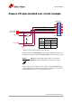
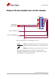
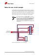
Camera I/O non-isolated user circuit example
The non-isolated trigger circuit is connected to a Texas Instruments
SN74LVC2G241 buffer/driver inside the camera. See the Texas Instruments
SN74LVC2G241 for more detailed information.
Figure 17: Prosilica GS non-isolated trigger user circuit
Caution
Input: Incoming trigger must be able to source 10 μA, at 3.3 V.
Input trigger voltage greater than 5.5 V will damage the cam-
era.
Output: The maximum sync output current is 24 mA, at 3.3 V.
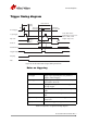
CABLE SIDE
IN 2 (3.3 V DRIVER)
CAMERA GND
3M 10114-3000PE
1
2
3
4
5
6
7
8
9
10
11
12
13
14
OUT 2 (3.3 V RECEIVER)
CAMERA POWER