8 - CD2 6 D1 - 1 3 Available in French Canadian (FC) Installer’s Guide Upflow / Horizontal and Downflow / Horizontal, Gas-Fired, Direct Vent, 2-Stage Condensing Furnaces with Variable Speed Inducer *UH2B060A9V3VA *UH2B080A9V3VA *UH2B080A9V4VA *UH2C100A9V4VA *UH2C100A9V5VA *UH2D120A9V5VA *DH2B060A9V3VA *DH2B080A9V3VA *DH2B080A9V4VA *DH2C100A9V4VA *DH2D120A9V5VA *__First letter may be “A” or “T” ALL phases of this installation must comply with NATIONAL, STATE AND LOCAL CODES IMPORTANT — This Document i
Installer’s Guide SAFETY SECTION ! WARNING ▲ CARBON MONOXIDE POISONING HAZARD Failure to follow the steps outlined below for each appliance connected to the venting system being placed into operation could result in carbon monoxide poisoning or death.
Installer’s Guide The following warning complies with State of California law, Proposition 65. ! WARNING ▲ This product contains fiberglass wool insulation! Fiberglass dust and ceramic fibers are believed by the State of California to cause cancer through inhalation. Glasswool fibers may also cause respiratory, skin, or eye irritation. Careful consideration must be taken in the installation process to avoid personal injury, property damage or equipment damage.
Installer’s Guide The following safety practices and precautions must be followed during the installation, servicing, and operation of this Furnace. 1. Use only with the type of gas approved for this Furnace. Refer to the Furnace rating plate. 2. Install this Furnace only in a location and position as specified in “Location and Clearances” (page 5) of these instructions. 3.
Installer’s Guide GENERAL INSTALLATION INSTRUCTIONS The manufacturer assumes no responsibility for equipment installed in violation of any code or regulation. It is recommended that Manual J of the Air Conditioning Contractors Association (ACCA) or A.R.I. 230 be followed in estimating heating requirements. When estimating heating requirements for installation at Altitudes above 2000 ft., remember the gas input must be reduced (See combustion and input check page 31).
Figure 2.
Figure 3.
Installer’s Guide Table 1 Required floor opening: (DOWNFLOW) INSTALLATION INSTRUCTIONS ! WARNING ▲ FIRE HAZARD. DO NOT INSTALL THE FURNACE DIRECTLY ON CARPETING, TILE OR OTHER COMBUSTIBLE MATERIAL OTHER THAN WOOD FLOORING. FOR VERTICAL DOWNFLOW APPLICATION, SUBBASE (BAYBASE205) MUST BE USED BETWEEN THE FURNACE AND COMBUSTIBLE FLOORING. WHEN THE DOWNFLOW FURNACE IS INSTALLED VERTICALLY WITH A CASED COIL, A SUBBASE IS NOT REQUIRED. The bottom panel of the upflow furnace must be removed for bottom return air.
Installer’s Guide The horizontal Furnace may also be suspended from the joists using all-thread rods with a substantial metal support frame that supports the entire length of the furnace. The rods need to be of sufficient length to allow for proper clearances from combustible materials. The frame needs to be at least 32" in length to allow for access to service panels. If the Furnace is suspended using steel strap, it must be supported at all four corners and in the middle at the front of the Furnace.
Installer’s Guide * Furnaces installed near chemical storage areas. Exposure to the following substances in the combustion air supply will also require OUTDOOR AIR for combustion: * Permanent wave solutions * Chlorinated waxes and cleaners * Chlorine based swimming pool chemicals * Water softening chemicals * Deicing salts or chemicals * Carbon Tetrachloride * Halogen type refrigerants * Cleaning solvents (such as perchloroethylene) * Printing inks, paint removers, varnish, etc.
Installer’s Guide Where there is no complete return duct system, the return connection must be run full size from the Furnace to a location outside the utility room, basement, attic, or crawl space. Do Not install return air through the back of the Furnace cabinet. Carbon monoxide, fire or smoke can cause serious bodily injury, death, and/or property damage.
Installer’s Guide The furnace and the bottom filter rack, BAYRACK960, installation can be seen in Figure 14. ALTERNATE FILTER RACK INSTALLATION FOR BOTTOM RETURN - BAYRACK960 The following checklist should be used when installing a return filter on an upflow furnace: a. Remove the filter. b. Remove the bottom panel. c. With the filter removed, the filter rack is compressed and then inserted into the bottom of the furnace.
Installer’s Guide Furnace Cabinet Side Filter Rack Retaining Screw/Pin SIDE CUTOUT Filter Rack low Airf RETAINING PIN (Both Sides) Engagement Hole For Filter Rack Installation With Bottom Return SPRINGS Bottom Panel BOTTOM PANEL INSTALLED BOTTOM ENGAGEMENT Figure 18 BLOWER DECK Engagement Hole For Filter Rack Installation With Side Return Furnace Blower Deck FILTER RACK RAILS Figure 21 Typical Upflow Right Side Return Filter Rack Installation Furnace Cabinet Side Airf low Filter Rack Retai
Installer’s Guide UPFLOW FILTER CLIP / BRACKET INSTALLATION 1. Determine the location to be used. The furnace cabinet has dimples for location of the furnace clips (Side return only). Pre-drill clearance holes with a 3/16" drill. Bottom return holes are pre-drilled. 2. Install the clips in front and rear of the desired location using the screws provided. The filter clip with the leaf spring mounts in the rear of the cabinet. See Figure 24.
Installer’s Guide GENERAL VENTING ! WARNING ▲ CARBON MONOXIDE POISONING HAZARD Failure to follow the steps outlined below for each appliance connected to the venting system being placed into operation could result in carbon monoxide poisoning or death. The following steps shall be followed for each appliance connected to the venting system being placed into operation, while all other appliances connected to the venting system are not in operation: 1. Seal any unused openings in the venting system. 2.
Installer’s Guide For DIRECT VENT APPLICATION: The Furnaces must be vented to the exterior of the house and combustion air MUST come through the inlet air pipe FROM OUTSIDE AIR. NOTE: BAYVENT200* accessories can be used for inlet and outlet terminals when the pipes do not exit the structure together. For Canadian applications ONLY, IPEX 196006 may be used for horizontal and vertical terminations. IPEX 081216, IPEX 081218, and IPEX 081219 may only be used for horizontal vent terminations.
Installer’s Guide VENT FITTING MATERIAL – PLASTIC Gas and liquid tight single wall vent fittings, designed for resistance to corrosive flue condensate, MUST be used throughout. Listed in Table 9, page 18, are designations for different types of 2" and 3" size pipe and fittings that meet these requirements. The materials listed are various grades of PVC, CPVC, and ABS plastic. PIPE JOINTS: All joints must be fastened and sealed to prevent escape of combustion products into the building.
Installer’s Guide Table 9 PVC VENT FITTING MATERIAL These fittings are available from your Gas Furnace Distributors.
Installer’s Guide Table 10 VENT LENGTH TABLE MAXIMUM TOTAL EQUIVALENT LENGTH IN FEET FOR VENT AND INLET AIR (SEE NOTES) ALTITUDE 0-7,000 Feet 2 INCH PIPE 2.5 INCH PIPE 3 or 4 INCH PIPE *UH/DH2B060A9V3VA 200 200 200 *UH/DH2B080A9V3VA *UH/DH2B080A9V4VA 50 120 200 *UH/DH2C100A9V4VA *UH2C100A9V5VA Not Allowed 60 200 *UH/DH2D120A9V5VA Not Allowed Not Allowed 200 7,000-9,500 Feet 2 INCH PIPE 2.
Installer’s Guide HORIZONTAL VENTING (Upflow/ Horizontal) ! CAUTION ▲ When the vent pipe is exposed to temperatures below freezing, e.g., when it passes through unheated spaces, etc., the pipe must be insulated with 1/2 inch (22.7 mm) thick Armaflex-type insulation or equal. If the space is heated sufficiently to prevent freezing, then the insulation will not be required. If domestic water pipes are not protected from freezing then the space meets the condition of a heated space.
Installer’s Guide ! CAUTION ▲ The vent for this appliance shall not terminate ANCHORS (4 req.) (1) Over public walways; or " 7.2 VENT PLATE VENT 3.2" 12" MINIMUM TO OVERHANG COMBUSTION AIR SCREWS (4 req.) VENT VENT CAP MAINTAIN 12" (18" FOR CANADA) MINIMUM CLEARANCE ABOVE HIGHEST ANTICIPATED SNOW LEVEL OR GRADE WHICHEVER IS GREATER Figure 32. BAYVENT200B For Canadian applications only, IPEX 196006, IPEX 081216, IPEX 081218, and IPEX 081219 may be used for horizontal vent terminations.
VENT TABLES Installer’s Guide 3. SIGNAGE. A metal or plastic identification plate shall be permanently mounted to the exterior of the building at a minimum height of eight (8) feet above grade directly in line with the exhaust vent terminal for the horizontally vented gas fueled heating appliance or equipment. The sign shall read, in print size no less than one-half (1/2) inch in size, “GAS VENT DIRECTLY BELOW. KEEP CLEAR OF ALL OBSTRUCTIONS”. 4. INSPECTION.
Installer’s Guide SUPPORT HORIZONTAL PIPE EVERY 3' 0" WITH THE FIRST SUPPORT AS CLOSE TO THE FURNACE AS POSSIBLE. INDUCED DRAFT BLOWER, HOUSING, AND FURNACE MUST NOT SUPPORT THE WEIGHT OF THE FLUE PIPE. Figure 36 VENT 12 INCHES MIN. CLEARANCE MUST BE MAINTAINED ABOVE HIGHEST ANTICIPATED SNOW LEVEL. MAXIMUM NOT TO EXCEED 24 INCHES ABOVE ROOF. MAINTAIN 12 IN. (18 IN. FOR CANADA) MINIMUM CLEARANCE ABOVE HIGHEST ANTICIPATED SNOW LEVEL. MAXIMUM OF 24 IN. ABOVE ROOF.
Installer’s Guide VENTING THROUGH THE ROOF When penetrating roof with a 2" PVC vent pipe, a 2" electrical conduit flashing may be used for a weather tight seal. Lubricate flexible seal on flashing before PVC pipe is pushed through the seal. (Field Supplied) NOTE: No vent cap as shown in Figure 37 is the preferred method for vertical vent termination in extremely cold climates. In extreme climate conditions, insulate the exposed pipe above the roof line with Armaflex type insulation.
Installer’s Guide INSIDE CORNER DETAIL G V H D E V B C V B V L I FIXED CLOSED B V OPERABLE F V X V X AIR SUPPLY INLET X V J K A B VENT TERMINAL V M B B V FIXED CLOSED OPERABLE AREA WHERE TERMINAL IS NOT PERMITTED Figure 42.
Installer’s Guide Table 14 Direct Vent Terminal Clearances Canadian Installations US Installations 12 inches (30 cm) 12 inches (30 cm) A= Clearance above grade, veranda, porch, deck, or balcony B= Clearance to window or door that may be opened C= Clearance to permanently closed window * * D= Vertical clearance to ventilated soffit located above the terminal within a horizontal distance of 2 feet (61 cm) from the center line of the terminal * * E= Clearance to unventilated soffit * * F=
Installer’s Guide CONDENSATE DRAIN INSTRUCTIONS Knock outs are provided on the left and right hand side of both furnace cabinets for drain connections IN VERTICAL APPLICATIONS. The standard arrangement is for the drain connection on the left side. The tubing may have to be trimmed in this application to avoid kinking. The upflow (vertical application) has provisions for right side drain connections by turning the trap and extending the tubing to the lower right front corner of the Furnace.
Installer’s Guide ALL HORIZONTAL APPLICATIONS ARE LEFT SIDE DRAIN ONLY HEADER TO OPEN/ VENTED DRAIN UPFLOW FURNACE ON LEFT SIDE WITH LEFT DRAIN SHOWN If upflow furnace is installed over a finished ceiling, overflow from the primary drain vent stack must flow into an auxillary drain pan to prevent damage to the finished ceiling below. Figure 45 IMPORTANT: The condensate drain should be installed with provisions to prevent winter freeze-up of the condensate drain line.
Installer’s Guide VERTICAL APPLICATIONS HORIZONTAL APPLICATIONS Upflow furnace - The connection tubing for left and right side drainage is shipped in the blower compartment. Install the connection tubing from the trap to the side of the unit and trim all excess tubing to avoid kinks. Upflow and Downflow furnaces - All horizontal applications are left side only. It is always recommended that the auxiliary drain pan be installed under a horizontally installed evaporator and/or 90% gas furnace.
Installer’s Guide the secondary recuperative cell. Remove the larger drain line (from the secondary cell) and trim to fit between the secondary cell and the new trap location. On upflow units, plug the hole in the blower deck where the tube went through. Remove the hose from the induced blower and reposition into the other drain tap of the inducer, which is located 90° clockwise around the inducer. Move the cap from that drain tap to the unused drain tap.
Installer’s Guide AUTOMATIC GAS VALVE WITH MANUAL SHUT-OFF AUTOMATIC GAS VALVE WITH MANUAL SHUT-OFF MAIN MANUAL SHUT-OFF VALVE MAIN MANUAL SHUT-OFF VALVE GROUND UNION JOINT GROUND UNION JOINT DRIP LEG DRIP LEG Figure 54. UPFLOW MAY BE LEFT OR RIGHT HAND GAS PIPING AUTOMATIC GAS VALVE WITH MANUAL SHUT-OFF AUTOMATIC GAS VALVE WITH MANUAL SHUT-OFF Figure 55.
Installer’s Guide Gas Piping ! WARNING ▲ HAZARD OF EXPLOSION! NEVER USE AN OPEN FLAME TO DETECT GAS LEAKS. EXPLOSIVE CONDITIONS MAY OCCUR. USE A LEAK TEST SOLUTION OR OTHER APPROVED METHODS FOR LEAK TESTING. FAILURE TO FOLLOW RECOMMENDED SAFE LEAK TEST PROCEDURES COULD RESULT IN DEATH OR SERIOUS INJURY OR EQUIPMENT OR PROPERTY-ONLY-DAMAGE. ! WARNING ▲ HAZARD OF EXPLOSION REPLACE AND/ OR TIGHTEN ALL PLUGS REMOVED OR LOOSENED WHEN ADJUSTING GAS PRESSURE.
Installer’s Guide 5. Adjust 1st stage gas heat by removing the low (LO) adjustment regulator cover screw. 2nd Stage (HI) Manifold Pressure Adjustment a. To increase outlet pressure, turn the regulator adjust screw clockwise. b. To decrease outlet pressure, turn the regulator adjust screw counterclockwise. c. Adjust regulator until pressure shown on manometer matches the pressure specified in Table 17. 1.
Installer’s Guide ! WARNING ▲ HAZARD OF EXPLOSION REPLACE AND/ OR TIGHTEN ALL PLUGS REMOVED OR LOOSENED WHEN ADJUSTING GAS PRESSURE. LEAK CHECK THE FITTINGS BEFORE PLACING THE FURNACE INTO REGULAR SERVICE. FAILURE TO FOLLOW THIS WARNING COULD RESULT IN FIRE, EXPLOSION, PROPERTY DAMAGE, OR DEATH. Figure 59 NOTE: The manifold pressure must be referenced to the burner box. The burner box pressure tap equalizes the gas valve pressure regulator.
Installer’s Guide HIGH ALTITUDE DERATE Table 21 Input ratings (BTUH) of these Furnaces are based on sea level operation and should not be changed at elevations up to 2,000 ft. If the installation is 2,000 ft. or above, the Furnace input rate (BTUH) shall be reduced 4% for each 1,000 ft. above sea level.
Installer’s Guide Electrical Connections Make wiring connections to the unit as indicated on enclosed wiring diagram. As with all gas appliances using electrical power, this furnace shall be connected into a permanently live electric circuit. It is recommended that furnace be provided with a separate “circuit protection device” electric circuit.
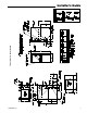
Installer’s Guide FIELD WIRING DIAGRAM FOR VARIABLE SPEED 2 STAGE FURNACE 2 STAGE HEATING USING A 2 STAGE HEATING THERMOSTAT NO COOLING 1. 2. 3. 4. 5. W14 6. W14 JUMPER SEE NOTE 9 7. 8. 9. Y1/Ylo SEE NOTE 7 B/C SEE NOTE 6 Be sure power agrees with equipment nameplates. Low voltage (24 volt wiring) to be No. 18 A.W.G. min. Grounding of equipment must comply with local codes. Set thermostat heat anticipator per unit wiring diagram. These leads provide 115V.
Installer’s Guide FIELD WIRING DIAGRAM FOR VARIABLE SPEED 2 STAGE FURNACE 1 STAGE HEATING, 1 STAGE COOLING USING A 1 STAGE HEATING, 1 STAGE COOLING THERMOSTAT (OUTDOOR SECTION WITHOUT TRANSFORMER) W14 W14 JUMPER SEE NOTE 9 OUTDOOR UNIT (NO TRANSFORMER) Y1/Ylo SEE NOTE 7 FIELD ADDED JUMPER W1 TO W2. SEE FURNACE WIRING DIAGRAM FOR 2ND STAGE TIMING. B/C SEE NOTE 6 TO 115 V 1 PH., 60 HZ., POWER SUPPLY PER LOCAL CODES B/C HUM SEE NOTE 5 EAC SEE NOTE 5 From Dwg. B342022 Rev.
Installer’s Guide FIELD WIRING DIAGRAM FOR VARIABLE SPEED 2 STAGE FURNACE 2 STAGE HEATING, 1 STAGE COOLING USING A 2 STAGE HEATING, 1 STAGE COOLING THERMOSTAT (OUTDOOR SECTION WITHOUT TRANSFORMER) W14 SEE NOTE 9 W14 JUMPER SEE NOTE 9 OUTDOOR UNIT (NO TRANSFORMER) Y1/Ylo SEE NOTE 7 B/C SEE NOTE 6 B/C TO 115 V 1 PH., 60 HZ., POWER SUPPLY PER LOCAL CODES HUM SEE NOTE 5 EAC SEE NOTE 5 From Dwg. B342020 Rev.
Installer’s Guide FIELD WIRING DIAGRAM FOR VARIABLE SPEED 2 STAGE FURNACE 2 STAGE HEATING, 2 STAGE COOLING (OUTDOOR SECTION WITHOUT TRANSFORMER) W14 OUTDOOR UNIT NO. 1 (NO TRANSFORMER) SEE NOTE 3 SEE NOTE 7 OUTDOOR UNIT NO. 2 (NO TRANSFORMER) TO 115 V 1 PH., 60 HZ., POWER SUPPLY PER LOCAL CODES B/C SEE NOTE 6 B/C HUM SEE NOTE 5 EAC SEE NOTE 5 From Dwg. B342018 Rev.
Installer’s Guide Start-up and Adjustment Preliminary Inspections ! WARNING ▲ ELECTRIC SHOCK HAZARD DISCONNECT POWER TO THE UNIT BEFORE REMOVING THE BLOWER DOOR. ALLOW A MINIMUM OF 10 SECONDS FOR IFC POWER SUPPLY TO DISCHARGE TO 0 VOLTS. FAILURE TO FOLLOW THIS WARNING COULD RESULT IN PROPERTY DAMAGE, PERSONAL INJURY OR DEATH. With gas and electrical power “OFF” 1. Duct connections are properly sealed 2. Filters are in place 3. Venting is properly assembled 4.
Installer’s Guide NOTE TO INSTALLER Review warnings and the contents of USER’S INFORMATION MANUAL with the homeowner when installation is complete and equipment is ready to be turned over to the homeowner for normal operation. CONTROL AND SAFETY SWITCH ADJUSTMENT LIMIT SWITCH CHECK OUT The limit switch is a safety device designed to close the Gas Valve should the Furnace become overheated.
Installer’s Guide INSTRUCTIONS TO THE OWNERS ! WARNING ▲ EXPLOSION HAZARD IN THE EVENT THAT ELECTRICAL, FUEL OR MECHANICAL FAILURES OCCUR, SHUT OFF THE GAS SUPPLY AT THE MANUAL GAS SHUT OFF VALVE, LOCATED ON THE SUPPLY GAS PIPING COMING INTO THE FURNACE, BEFORE TURNING OFF THE ELECTRICAL POWER TO THE FURNACE. CONTACT SERVICER. FAILURE TO FOLLOW THIS WARNING COULD RESULT IN PROPERTY DAMAGE, PERSONAL INJURY OR DEATH.
Table 23 INTEGRATED FURNACE CONTROL LED FLASH CODES RED LED - LitePortTM DATA - 1 FLASH EVERY 20 SECONDS 2 Flashes --RETRIES OR RECYCLES EXCEEDED 3 Flashes --INDUCER OR PRESSURE SWITCH ERROR 4 Flashes --OPEN LIMIT OR ROLLOUT SWITCH 5 Flashes --FLAME SENSED WHEN NO FLAME SHOULD BE PRESENT 6 Flashes --LINE REVERSE POLARITY 7 Flashes --GAS VALVE CIRCUIT ERROR 8 Flashes --WEAK FLAME 9 Flashes --OPEN INDUCER LIMIT ERROR GREEN LED - STATUS Slow Flash NORMAL, NO CALL FOR HEAT Fast Flash NORMAL, CALL FOR HEAT PRES