
Specifications


Camera interfaces
Pearleye Technical Manual V2.0.0
23
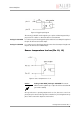
Control connector
Camera I/O connector pin assignment (15-pin
D-Sub jack)
This jack is intended for the power supply as well as for controlling the camera
via its serial RS232 interface over a COM port.
Furthermore some output signals are available, showing the camera state.
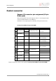
Figure 4: Camera I/O connector pin assignment (Pearleye P-007 LWIR / Pearleye P-030 LWIR)
Pearleye P-007 LWIR / Pearleye P-030 LWIR
Pin Signal Direction Level Description
1
External Power +12 V DC (-0% / +5%)
Power supply
max. 1.5 A
2
3
External GND
4
5 --- Reserved
(do not connect)
6 --- Reserved
(do not connect)
7 RxD In RS232 Camera control
8TxD Out RS232 Camera control
9
--- Reserved
(do not connect)
10
Trigger (Reset)
input
-
optocoupler input
11 +
12 Sensor tempera-
ture too low
- optocoupler output
13 +
14 Sensor tempera-
ture too high
Out Active low
15 Frame-sync
output
Out Active low