
Instruction manual

Camera interfaces
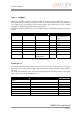
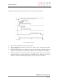
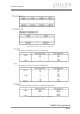
7.5.2 Outputs
n-inverting outputs with open emitters. These are shown in the following
oltage 45 V
ferent to the AVT Dolphin series to achieve higher output
swing.
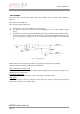
ndin voltage ap t OutVCC and the t f inpu to drive,
e c sistor in se betwe The
use of 1 kΩ@ 5V or 2.4 kΩ@ 12V can be recommended. Typical delay is not more than 40
µs.
The camera has 2 no
diagram:
Max. emitter current 500 mA
Max. collector emitter v
Voltage above +45 V may damage the optical coupler.
The output connection is dif
Depe g on the plied a ype o t which you want
it may b necessary to swit h an external re ries en GPOutl and ground.
Figure 24: Output schematics
Output features are configured by software. Any signal can be placed on any output.
The main features of output signals are described below:
IntEna (Integration Enable) Signal
This signal displays the time in which exposure was made. By using a register this output can be
delayed by up to 1.05 seconds.
Fval (Frame valid) Signal
This feature signals readout from the sensor. This signal Fval follows IntEna.
Busy Signal
This indicator appears when the exposure is being made; the sensor is being read from or data
transmission is active. The camera is busy.
MARLIN Technical Manual
Page 44