
Instruction manual

Camera interfaces
7.5.1.1 Triggers
All inputs configured as triggers are linked by AND. If several inputs are being used as triggers, a
high signal must be present on all inputs in order to generate a trigger signal. The polarity for
each signal can be set separately via the inverting inputs. The camera must be set to "external
iggering" to trigger image capture by the trigger signal.
over th se plug are controlled by an advanced feature
tr
All input and output signals running e HiRo
register.
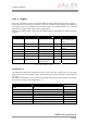
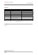
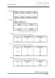
Register Name Field Bit Description
0xF1000300 Prese 0 IO_INP_CTRL1 nce_Inq [ ] Indicates presence of
this feature (read
only)
--- [1..6]
Polarity [7] , 1: high 0: low active
active
--- [8..10]
InputMo [1 ] de 1..15 Mode
--- [16..30]
PinState [31] nt state of RD: Curre
pin
0xF1000304 IO_INP_CTRL2 Same as
IO_INP_CTRL1
Table 17: Input configuration register
IO_INP_CTRL 1-2
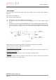
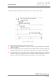
The Polarity flag determines whether the input is low active (0) or high t
can be seen in the following table. The Pi s u er of
the input.
PinState bit refers to the inverted output side of the optical coupler. This signals
that an open input sets the PinState bit to “1”.
active (1). The inpu
mode nState flag i sed to qu y the current status
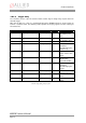
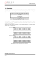
For inputs the
ID Mode
Default
0x00
Off
0x01 reserved
0x02 Trigger input Input 1
0x03 reserved
0x04 reserved
0x05 tbd (SPI external DCLK)
0x06..0x0F reserved
0x10..0x1F reserved
Table 18: Input routing
MARLIN Technical Manua
l
Page 41