
Instruction manual

Prosilica GX Technical Manual V2.2.0
72
Description of the data path
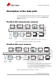
Description of the data path
The following diagrams illustrate the data flow and the bit resolution of image
data. The individual blocks are described in more detail in the GigE Features
Reference document.
Prosilica GX: monochrome cameras
Prosilica GX: color cameras
Figure 54: Block diagram of Prosilica GX monochrome cameras
Figure 55: Block diagram of Prosilica GX color cameras
Sensor
Analog Analog
ADC
HIROSE I/O
RS232
Analog Analog
Gain
Camera control
Vertical
binning /
Vertical ROI
14 bit
14 bit
GigE
14 bit
Frame
memory
Gigabit
Ethernet
interface
‡
Factory calibrated. NOT a user control.
Horizontal
binning
14 bit 14 bit
Defect
§
mask
Horizontal
ROI
Oset
‡
§
Defect masking is not available for GX1050, GX1660, and GX1910
HIROSE I/O
RS232
Sensor
Analog
Analog
ADC
GigE
14 bit
Analog Analog
Gain
Horizontal
binning*
Vertical
binning* /
Vertical ROI
14 bit
Gigabit
Ethernet
interface
14 bit
White balance
8/12 bit8/12/14 bit
Frame
memory
Bayer
†
Interpolation
3 X 3
‡
Factory calibrated. NOT a user control.
†
For on-camera interpolated PixelFormats only—outputs 8 bit.
On-camera interpolated PixelFormat, RGB12Packed—outputs 12 bit.
Raw un-interpolated PixelFormats skip this block—outputs 8/12 bit
depending upon the bit depth of PixelFormat used.
14 bit
Defect
§
mask
14 bit
Camera control
Horizontal
ROI
§
Defect masking is not available for GX1050C, GX1660C, and GX1910C
Oset
‡
*
Color information lost while binning is active.