
Instruction manual

Prosilica GX Technical Manual V2.2.0
42
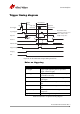
Camera interfaces
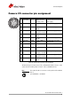
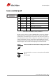
Camera I/O connector pin assignment
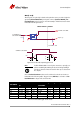
The General Purpose I/O port uses a Hirose HR10A-10R-12PB connector on the
camera side. The mating cable connector is Hirose HR10A-10P-12S.
Pin Signal Direction Level Description
1 Camera GND In GND for RS-232
and ext. power
Ground for RS-232 and camera
power supply
2 Camera Power In 5–24 VDC Camera power supply
3 Out 4 Out Open emitter max.
20 mA
Output 4 isolated (SyncOut4)
4In 1 In U
in
(high) = 5–24 V
U
in
(low) = 0–0.8 V
Input 1 isolated (SyncIn1)
5 Out 3 Out Open emitter max.
20 mA
Output 3 isolated (SyncOut3)
6 Out 1 Out Open emitter max.
20 mA
Output 1 isolated (SyncOut1)
7 Isolated IO
GND
In/Out Common GND for
In/Out
Isolated input and output
signal ground
8 RxD RS-232 In RS-232 Terminal receive data
9 TxD RS-232 Out RS-232 Terminal transmit data
10 Isolated Out
Power
In Common VCC for
outputs 5–24 V DC
Power input for digital outputs
11 In 2 In U
in
(high) = 5–24 V
U
in
(low) = 0–0.8 V
Input 2 isolated (SyncIn2)
12 Out 2 Out Open emitter max.
20 mA
Output 2 isolated (SyncOut2)
Table 13: Camera I/O connector pin assignment
Note
This cable side Hirose connector can be purchased from Allied
Vision.
P/N: K7600040 or 02-7002A
1
9
8
7
6
5
4
3
2
11
12
10