Allied Vision Prosilica GX Technical Manual GigE Vision Cameras V2.2.
Legal notice For customers in the U.S.A. This equipment has been tested and found to comply with the limits for a Class A digital device, pursuant to Part 15 of the FCC Rules. These limits are designed to provide reasonable protection against harmful interference when the equipment is operated in a residential environment.
Contents Contacting Allied Vision .................................................................................. 5 Introduction ............................................................................................................ 6 Document history............................................................................................................ 6 Manual conventions......................................................................................................... 8 Precautions.....
Firmware update .................................................................................................51 Resolution and ROI frame rates ...............................................................52 Prosilica GX1050 ........................................................................................................... 54 Prosilica GX1660 ........................................................................................................... 56 Prosilica GX1910 .........................
Contacting Allied Vision Contacting Allied Vision Info • Technical information: http://www.alliedvision.com • Support: support@alliedvision.com Allied Vision Technologies GmbH (Headquarters) Taschenweg 2a 07646 Stadtroda, Germany Tel.: +49 36428-677-0 Fax: +49 36428-677-28 e-mail: info@alliedvision.com Allied Vision Technologies Canada Inc. 101-3750 North Fraser Way Burnaby, BC, V5J 5E9, Canada Tel.: +1 604-875-8855 Fax: +1 604-875-8856 e-mail: info@alliedvision.com Allied Vision Technologies Inc.
Introduction Introduction This Prosilica GX Technical Manual describes in depth the technical specifications of the Prosilica GX camera family including dimensions, feature overview, I/O definition, trigger timing waveforms, and frame rate performance. For information on software installation read the GigE Installation Manual. For detailed information on camera features and controls specific to the Prosilica GX refer to the GigE Features Reference and GigE Camera and Driver Attributes documents.
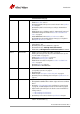
Introduction Version V2.0.5 Date 2013-Jun-06 Remarks • • • • • • • V2.0.6 2013-Jul-05 • • • • V2.0.7 2013-Oct-02 • • • • • • • V2.0.8 2013-Nov-26 • • • • V2.1.0 2015-Mar-10 • • • • • continued from last page Updated the RoHS directive Added Status LEDs section Updated bit depth and exposure control values in the Specifications chapter Updated the pixel format naming according to the GenICam standard Added frame rate vs.
Introduction Version Date Remarks V2.1.0 2015-Mar-10 [Continued] [Continued] • • • Updated orientation of the connector diagram on page 42 Renamed Truesense references to OnSemi Updated datapath diagram for Prosilica GX: color cameras V2.2.
Introduction www This symbol highlights URLs for further information. The URL itself is shown in blue. Example: http://www.alliedvision.com Precautions Caution Do not disassemble the camera housing. Warranty is void if camera has been disassembled. This camera contains sensitive internal components. Caution Keep shipping material. Poor packaging of the product may cause damage during shipping. Caution Verify all external connections.
Introduction Cleaning optics Caution Caution Allied Vision does not warranty against any physical damage to the sensor/filter/protection glass or lenses. Use utmost care when cleaning optical components. Do not touch any optics with fingers. Oil from fingers can damage fragile optical coatings. Identifying debris Debris on the image sensor or optical components appears as a darkened area or smudge on a camera image. Do not confuse this with a pixel defect which appears as a distinct point.
Introduction Cleaning with air Blow directly on the contaminated surface with moderate pressure, clean compressed air. Caution Do not exceed 6 bar (90 psi). If using canned air, approximately ~ 4.8 bar (70 psi) when full, do not shake or tilt the can, as extreme changes in temperature due to sudden cold air can crack the optic glass. View a live image with the camera after blowing. If debris is still present, repeat the process until it is determined that the particulate cannot be dislodged.
Conformity Conformity Allied Vision Technologies declares under its sole responsibility that all standard cameras of the Allied Vision Prosilica GX family, to which this declaration relates, are in conformity with the following standard(s) or other normative document(s): • CE, following the provisions of 2004/108/EG directive • FCC Part 15 Class A • RoHS (2011/65/EU) We declare, under our sole responsibility, that the previously described Allied Vision Prosilica GX cameras conform to the directives of the
Specifications Specifications Prosilica GX1050/1050C Feature Resolution Specification 1024 x 1024 Sensor OnSemi KAI-01050 Type CCD Progressive Sensor size Type 1/2 Cell size 5.
Specifications 60% Measured with AR coated cover glass Quantum Efficiency 50% 40% 30% 20% 10% 0% 350 400 450 500 550 600 650 700 750 800 850 900 950 1000 1050 1100 Wavelength [nm] Figure 1: Prosilica GX1050 monochrome spectral response Red 45% Green Blue Measured with AR coated cover glass Quantum Efficiency 40% 35% 30% 25% 20% 15% 10% 5% 0% 400 500 600 700 800 Wavelength [nm] 900 1000 1100 Figure 2: Prosilica GX1050C color spectral response (without IR cut filter) Prosilica GX Technical M
Specifications Prosilica GX1660/1660C Feature Specification Resolution 1600 x 1200 Sensor OnSemi KAI-02050 Type CCD Progressive Sensor size Type 2/3 Cell size 5.
Specifications 60% Measured with AR coated cover glass Quantum Efficiency 50% 40% 30% 20% 10% 0% 350 450 550 650 750 850 Wavelength [nm] 950 1050 1150 Figure 3: Prosilica GX1660 monochrome spectral response Red 45% Green Blue Measured with AR coated cover glass 40% Quantum Efficiency 35% 30% 25% 20% 15% 10% 5% 0% 400 500 600 700 800 Wavelength [nm] 900 1000 1100 Figure 4: Prosilica GX1660C color spectral response (without IR cut filter) Prosilica GX Technical Manual V2.2.
Specifications Prosilica GX1910/1910C Feature Specification Resolution 1920 x 1080 Sensor OnSemi KAI-02150 Type CCD Progressive Sensor size Type 2/3 Cell size 5.
Specifications 50% Measured with AR coated cover glass 45% 40% Quantum Efficiency 35% 30% 25% 20% 15% 10% 5% 0% 350 450 550 650 750 Wavelength [nm] 850 950 1050 Figure 5: Prosilica GX1910 monochrome spectral response Red 40% Green Blue Measured with clear cover glass 35% Quantum Efficiency 30% 25% 20% 15% 10% 5% 0% 375 475 575 675 775 Wavelength [nm] 875 975 1075 Figure 6: Prosilica GX1910 color spectral response (without IR cut filter) Prosilica GX Technical Manual V2.2.
Specifications Prosilica GX1920/1920C Feature Specification Resolution 1936 x 1456 Sensor Sony ICX674 Type CCD Progressive Sensor size Type 2/3 Cell size 4.
Specifications 70% 60% Quantum Efficiency 50% 40% 30% 20% 10% 0% 400 500 600 700 Wavelength [nm] 800 900 1000 650 700 Figure 7: Prosilica GX1920 monochrome spectral response Red Green Blue 60% Quantum Efficiency 50% 40% 30% 20% 10% 0% 400 450 500 550 600 Wavelength [nm] Figure 8: Prosilica GX1920C color spectral response (without IR cut filter) Prosilica GX Technical Manual V2.2.
Specifications Prosilica GX2300/2300C Feature Specification Resolution 2336 x 1752 Sensor OnSemi KAI-04050 Type CCD Progressive Sensor size Type 1 Cell size 5.
Specifications 60% Measured with AR coated cover glass Quantum Efficiency 50% 40% 30% 20% 10% 0% 350 500 650 800 Wavelength [nm] 950 1100 Figure 9: Prosilica GX2300 monochrome spectral response Red Green Blue 45% Measured with AR coated cover glass 40% Quantum Efficiency 35% 30% 25% 20% 15% 10% 5% 0% 400 500 600 700 800 Wavelength [nm] 900 1000 1100 Figure 10: Prosilica GX2300C color spectral response (without IR cut filter) Prosilica GX Technical Manual V2.2.
Specifications Prosilica GX2750/2750C Feature Specification Resolution 2750 x 2200 Sensor Sony ICX694 Type CCD Progressive Sensor size Type 1 Cell size 4.
Specifications 70% 60% Quantum Efficiency 50% 40% 30% 20% 10% 0% 400 500 600 700 Wavelength [nm] 800 900 1000 650 700 Figure 11: Prosilica GX2750 monochrome spectral response Red Green Blue 70% 60% Quantum Efficiency 50% 40% 30% 20% 10% 400 450 500 550 Wavelength [nm] 600 Figure 12: Prosilica GX2750C color spectral response (without IR cut filter) Prosilica GX Technical Manual V2.2.
Specifications Prosilica GX3300/3300C Feature Specification Resolution 3296 x 2472 Sensor Cameras with P/N 02-2408D, 02-2409D: OnSemi KAI-08051 Cameras with P/N 02-2408B, 02-2409B: OnSemi KAI-08050 Type Sensor size Cell size Lens mount Max frame rate at full resolution A/D On-board FIFO Bit depth CCD Progressive Type 4/3 5.5 μm F 14.7 fps (1 port), 17.
Specifications 60% Measured with AR coated cover glass Quantum Efficiency 50% 40% 30% 20% 10% 0% 350 500 650 800 Wavelength [nm] 950 1100 Figure 13: Prosilica GX3300 monochrome spectral response Red Green Blue 45% Measured with AR coated cover glass 40% Quantum Efficiency 35% 30% 25% 20% 15% 10% 5% 0% 400 500 600 700 800 Wavelength [nm] 900 1000 1100 Figure 14: Prosilica GX3300C color spectral response (without IR cut filter) Prosilica GX Technical Manual V2.2.
Specifications Prosilica GX6600/6600C Feature Specification Resolution 6576 x 4384 Sensor OnSemi KAI-29050 Type CCD Progressive Sensor size Type 35 mm Cell size 5.
Specifications 50% Measured with AR coated cover glass Quantum Efficiency 40% 30% 20% 10% 0% 350 500 650 800 Wavelength [nm] 950 1100 Figure 15: Prosilica GX6600 monochrome spectral response Red 45% Green Blue Measured with AR coated cover glass 40% Quantum Efficiency 35% 30% 25% 20% 15% 10% 5% 0% 400 500 600 700 800 Wavelength [nm] 900 1000 1100 Figure 16: Prosilica GX6600C color spectral response (without IR cut filter) Prosilica GX Technical Manual V2.2.
Camera attribute highlights Camera attribute highlights Allied Vision cameras support a number of standard and extended features. The table below identifies a selection of interesting capabilities of the Prosilica GX camera family.
Filters Filters All Prosilica GX color models are equipped with an infrared block filter (IR filter). This filter is employed to prevent infrared wavelength photons from passing to the sensor. In the absence of IR filter, images are dominated by red and incapable of being properly color balanced. Monochrome cameras do not employ an IR filter. The figure below shows the filter transmission response for the IRC30 filter employed in the Prosilica GX cameras.
Camera dimensions Camera dimensions The Prosilica GX family supports a range of sensor configurations. The mechanical drawings in this section reflect the following configurations: • C-Mount (adjustable) • F-Mount • GX1920 and GX2750 Prosilica GX C-Mount: GX1050, GX1660, GX1910, GX2300 12.5 26 M3X4 (2x) 107.2 M2x3 (4x) 14 27.8 31.6 14 20 16 26 33 26.7 22.1 20.8 Adjustable C-Mount 8.9 90.9 5.1 9.9 34 38 53.3 M3x4 (8x) 26 26 M3x4 (4x) 2.5 85.9 12.
Camera dimensions Prosilica GX F-Mount: GX2300, GX3300 41.6 M3x4 (2x) 26 136.3 14 Adjustable Nikon F-Mount 10 27.8 M2x3 (4x) 14 20 20.8 22.1 33 90.9 8.9 59.7 39.1* 53.3 26 M3x4 (4x) 2.5 26 85.9 *Nominal adjustable 41.6 Figure 19: Prosilica GX F-Mount mechanical dimensions Note Prosilica GX cameras are shipped with an adjustable C-Mount or F-Mount. The camera can also be built with a CS-Mount upon request. Prosilica GX Technical Manual V2.2.
Camera dimensions Prosilica GX1920 and GX2750 13.4 26 M3X4 (2X) 108.1 M2X3 (4X) Adjustable C-Mount 14 27.8 31.6 14 20 16 26 33 26.7 22.1 20.8 8.9 5.1 92.2 9.6 26 34 38 53.3 M3X4 (8X) 26 M3X4 (4X) 2.5 85.9 13.4 Figure 20: Prosilica GX1920 and GX2750 models mechanical dimensions Note Prosilica GX1920 and GX2750 are 1.3 mm longer than the remaining GX C-Mount models. The same tripod adapter can be used with all GX cameras. Prosilica GX Technical Manual V2.2.
Camera dimensions Prosilica GX6600 2.5 M3x4 (4x) 88.9 38.9 26 26 136.6 14 Adjustable Nikon F-Mount 27.8 M2x3 (4x) 14 53.3 20 23.3 24.6 8.9 93.9 53.3 26 M3x4 (4x) 2.5 59.7 36.3* 26 88.9 *Nominal adjustable 38.6 Figure 21: Prosilica GX6600 models mechanical dimensions Note Prosilica GX6600 is taller than the remaining GX C-Mount models. Prosilica GX Technical Manual V2.2.
Camera dimensions Tripod adapter For GX1050, GX1660, GX1910, GX1920, GX2300 and GX3300 A Prosilica GX camera can be mounted on a camera tripod by using a mounting plate. The GX1050, GX1660, GX1910, GX1920, GX2300 and GX3300 models can use the mounting plate 02-5030A Note Prosilica GX tripod mount is available for purchase from Allied Vision. P/N: 02-5030A 6 SECTION A-A 3 9 0.5x 45° TYP 5.1 7 1/4-20 UNC 5 2x 6 30 22.9 2.5 2.5 A A 44 36.1 26 24 20.3 4X R1.5 2 28 42 4X R3 4X 3.4 90.
Camera dimensions For GX6600 Adjustment of lens mount model camera can be mounted on a camera tripod by using mounting plate 02-5034A. Note Prosilica GX6600 tripod mount is available for purchase from Allied Vision. P/N: 02-5034A 6 SECTION A-A 3 9 0.5 X 45° TYP 5.1 7 1/4-20 UNC 5 A 2x 6 30 18.3 2.5 2.5 2 A A 24 26 44 36.1 26 20.3 28 42 4X R1.5 4X R3 4X 3.4 94 A Figure 23: Prosilica GX6600 tripod mount mechanical drawing Prosilica GX Technical Manual V2.2.
Camera dimensions C-Mount flange focal distance Flange focal distance is the optical distance from the mounting flange to image sensor die. Prosilica GX C-Mount cameras are optically calibrated to a standard 17.526 mm optical flange focal distance, with a ±10 μm tolerance. www Prosilica GX cameras are shipped with adjustable C-Mount. The camera can also be built with a CS-Mount with a standard 12.50 mm optical flange focal distance and a ± 10 μm tolerance.
Camera dimensions Image to infinity Use a C-Mount compatible lens that allows an infinity focus. Set the lens to infinity and image a distant object—10 to 15 m should suffice. Make sure the lens is firmly threaded onto the C-Mount ring. Rotate the lens and C-Mount ring until the image is focused. Carefully tighten the locking ring and recheck focus.
Camera dimensions F-Mount flange focal distance Flange focal distance is the optical distance from the mounting flange to image sensor die. Prosilica GX F-Mount cameras are optically calibrated to a standard 46.5 mm optical flange focal distance. Adjustment of F-Mount The F-Mount is adjusted at the factory and should not require adjusting. If for some reason, the lens mount requires adjustment, use the following method.
Camera interfaces Camera interfaces This chapter provides information on Gigabit Ethernet port, inputs and outputs, and trigger features. www Accessories: Please contact Allied Vision sales representative or your local Allied Vision dealer for information on accessories: http://www.alliedvision.com/en/about-us/where-weare.
Camera interfaces Gigabit Ethernet port The Gigabit Ethernet port conforms to the IEEE 802.3 1000BASE-T standard for Gigabit Ethernet over copper. Allied Vision recommends using Category 6 or higher compatible cabling and connectors for best performance. The Prosilica GX offers two Gigabit Ethernet ports. This interface is enabled using Link aggregation. A link aggregation group (LAG) is automatically configured on the camera when both ports are connected.
Camera interfaces Camera I/O connector pin assignment 5 4 6 12 11 3 7 8 10 2 9 1 Pin Signal Direction Level Description 1 Camera GND In 2 Camera Power In GND for RS-232 and ext. power 5–24 VDC Ground for RS-232 and camera power supply Camera power supply 3 Out 4 Out Output 4 isolated (SyncOut4) 4 In 1 In 5 Out 3 Out 6 Out 1 Out 7 In/Out 8 Isolated IO GND RxD RS-232 In Open emitter max. 20 mA Uin(high) = 5–24 V Uin(low) = 0–0.8 V Open emitter max. 20 mA Open emitter max.
Camera interfaces I/O definition Camera Power The Prosilica GX camera family supports a wide input power voltage range. The camera will not power in reverse polarity. Exceeding the voltage range specified below will damage the camera. Caution 5–24 V. 12 V nominal. Note A 12 V power adapter with Hirose connector can be ordered from Allied Vision: • • P/N 02-8003A North America Supply. P/N 02-8004A Universal Supply.
Camera interfaces Input triggers In 1 and In 2 In 1 and In 2 allow the camera to be synchronized to some external event. These signals are optically isolated and require the signal common (Isolated IO GND). The camera can be programmed to trigger on the rising or falling edge of these signals. The camera can also be programmed to capture an image at some programmable delay time after the trigger event. These signals can be driven from 5 V to 24 V with a minimum current source of 5 mA. VDD+3.
Camera interfaces Out (1 to 4) These signals are optically isolated and require the user to provide a high voltage level (Isolated Out Power) and signal common (Isolated IO GND). Isolated Out Power can be from 5 V to 24 V. An example of the functional circuit is indicated in the diagram below. CAMERA INTERNAL EXTERNAL ISOLATED OUT POWER 3.
Camera interfaces Lens control port 1 2 3 4 5 6 7 8 Pin Signal Direction Description 1 Iris + Out Open Iris 2 Iris - Out Close iris 3 Focus + Out Focus far 4 Focus - Out Focus close 5 Zoom + Out Zoom out 6 Zoom - Out Zoom in 7 Video Iris Out PWM Signal for Iris Control 8 External GND --- External Ground for all lens control signals Table 15: Prosilica GX lens connector definition The lens control connector is a Hirose 3260-8S3.
Camera interfaces Video iris connection Prosilica GX cameras provide built-in auto iris controls for controlling videotype auto-iris lenses. These lenses are available from many popular security lens companies including Pentax, Fujinon, Tamron, Schneider and others. Remote iris lens control allows the camera to be more adaptable to changing light conditions. It allows the user to manually control the exposure and gain values and rely solely on the auto iris for adjustment to ambient lighting.
Camera interfaces Motorized lens connection TV ZOOM LENS BIPOLAR TYPE ZOOM+ ZOOMFOCUS+ FOCUSIRIS+ IRISCOMMON IRISFOCUSZOOMCOMMON 2 4 6 8 1 3 5 7 IRIS+ FOCUS+ ZOOM+ HIROSE 3240-8P-C(50) TV ZOOM LENS UNIPOLAR TYPE ZOOM FOCUS IRIS COMMON COMMON COMMON COMMON COMMON 2 4 6 8 1 3 5 7 IRIS FOCUS ZOOM HIROSE 3240-8P-C(50) Figure 31: Prosilica GX motorized lens connection diagram Caution WARNING Verify lens voltage setting on camera does not exceed lens voltage specification.
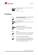
Camera interfaces Trigger timing diagram Readout time Trigger latency Tpd Registered exposure time Exposure start delay User trigger Note: Jitter at the beginning of an exposure has no effect on the length of exposure.
Camera interfaces Term Definition Trigger ready Indicates to the user that the camera will accept the next trigger Registered exposure time Exposure time value currently stored in the camera memory Exposure start delay Registered exposure time subtracted from the readout time and indicates when the next exposure cycle can begin such that the exposure will end after the current readout Interline time Time between sensor row readout cycles Imaging High when the camera image sensor is either exposi
Firmware update Firmware update Firmware updates are carried out via the GigE connection. Allied Vision provides an application for all Prosilica GX cameras that loads firmware to the camera using a simple interface. New feature introductions and product improvements motivate new firmware releases. All users are encouraged to use the newest firmware available and complete the firmware update if necessary. www Download the latest GigE firmware loader from the Allied Vision website: http://www.
Resolution and ROI frame rates Resolution and ROI frame rates This section provides performance information about the impact of reducing the region of interest on the camera’s maximum frame rate. In addition, because the Prosilica GX camera offers Dual GigE LAG, the impact of using a single Ethernet connection versus dual Ethernet connections with the host is compared.
Resolution and ROI frame rates Note For some GX cameras, e.g. GX1910, GX2300, bandwidth limiting occurs even in 8-bit pixel formats, although not as severely as with a 16-bit pixel format. The Prosilica GX camera can be operated near peak sensor frame rates even when using a single port connection. The frame rate vs. height graphs included in this section provide frame rate performance results for both single GigE port and Dual GigE LAG configurations at 8-/16-bit output formats.
Resolution and ROI frame rates Prosilica GX1050 8-bit output format Dual GigE - 8 bit 400 Single GigE - 8 bit Frame Rate [fps] 350 300 250 200 150 100 0 150 300 450 600 Height [pixels] 750 900 1050 Figure 34: Frame rate vs.
Resolution and ROI frame rates 16-bit output format Dual GigE - 16 bit Frame Rate [fps] 400 Single GigE - 16 bit 350 300 250 200 150 100 50 0 150 300 450 600 Height [pixels] 750 900 1050 Figure 35: Frame rate vs.
Resolution and ROI frame rates Prosilica GX1660 8-bit output format Dual GigE - 8 bit Frame Rate [fps] 260 Single GigE - 8 bit 220 180 140 100 60 0 200 400 600 Height [pixels] 800 1000 1200 Figure 36: Frame rate vs.
Resolution and ROI frame rates 16-bit output format Dual GigE - 16 bit 270 Single GigE - 16 bit Frame Rate [fps] 230 190 150 110 70 30 0 200 400 600 Height [pixels] 800 1000 1200 Figure 37: Frame rate vs.
Resolution and ROI frame rates Prosilica GX1910 Frame Rate [fps] 8-bit output format Dual GigE - 8 bit 275 250 225 200 175 150 125 100 75 50 0 100 200 300 Single GigE - 8 bit 400 500 600 Height [pixels] 700 800 900 1000 1100 Figure 38: Frame rate vs.
Resolution and ROI frame rates Frame Rate [fps] 16-bit output format Dual GigE - 16 bit 275 250 225 200 175 150 125 100 75 50 25 0 100 200 300 400 Single GigE - 16 bit 500 600 700 Height [pixels] 800 900 1000 1100 Figure 39: Frame rate vs.
Resolution and ROI frame rates Prosilica GX1920 8-bit output format Dual GigE - 8 bit Frame Rate [fps] 140 Single GigE - 8 bit 120 100 80 60 40 0 250 500 750 Height [pixels] 1000 1250 1500 Figure 40: Frame rate vs.
Resolution and ROI frame rates 16-bit output format Dual GigE - 16 bit 140 Single GigE - 16 bit Frame Rate [fps] 120 100 80 60 40 20 0 250 500 750 Height [pixels] 1000 1250 1500 Figure 41: Frame rate vs.
Resolution and ROI frame rates Prosilica GX2300 8-bit output format Dual GigE - 8 bit 130 Single GigE - 8 bit Frame Rate [fps] 115 100 85 70 55 40 25 0 200 400 600 800 1000 Height [pixels] 1200 1400 1600 1800 Figure 42: Frame rate vs.
Resolution and ROI frame rates 16-bit output format Dual GigE - 16 bit 130 Single GigE - 16 bit Frame Rate [fps] 110 90 70 50 30 10 0 300 600 900 Height [pixels] 1200 1500 1800 Figure 43: Frame rate vs.
Resolution and ROI frame rates Prosilica GX2750 8-bit output format Dual GigE - 8 bit 85 Single GigE - 8 bit Frame Rate [fps] 75 65 55 45 35 25 15 0 200 400 600 800 1000 1200 1400 1600 1800 2000 2200 Height [pixels] Figure 44: Frame rate vs.
Resolution and ROI frame rates 16-bit output format Dual GigE - 16 bit 80 Single GigE - 16 bit Frame Rate [fps] 70 60 50 40 30 20 10 0 200 400 600 800 1000 1200 1400 1600 1800 2000 2200 Height [pixels] Figure 45: Frame rate vs.
Resolution and ROI frame rates Prosilica GX3300 8-bit output format Dual GigE - 8 bit 70 Single GigE - 8 bit Frame Rate [fps] 60 50 40 30 20 10 0 500 1000 1500 Height [pixels] 2000 2500 Figure 46: Frame rate vs.
Resolution and ROI frame rates 16-bit output format Dual GigE - 16 bit 70 Single GigE - 16 bit Frame Rate [fps] 60 50 40 30 20 10 0 0 500 1000 1500 Height [pixels] 2000 2500 Figure 47: Frame rate vs.
Resolution and ROI frame rates Prosilica GX6600 8-bit output format Dual GigE - 8 bit 18 Single GigE - 8 bit Frame Rate [fps] 16 14 12 10 8 6 4 0 500 1000 1500 2000 2500 Height [pixels] 3000 3500 4000 4500 Figure 48: Frame rate vs.
Resolution and ROI frame rates 16-bit output format Dual GigE - 16 bit 18 Single GigE - 16 bit Frame Rate [fps] 16 14 12 10 8 6 4 2 0 550 1100 1650 2200 2750 Height [pixels] 3300 3850 4400 Figure 49: Frame rate vs.
Resolution and ROI frame rates Prosilica GX model comparison Single GigE port (8 bit) operation GX1050 GX1660 GX1910 GX1920 GX2300 GX2750 GX3300 GX6600 Frame Rate [fps] 1000 100 10 1 0 500 1000 1500 2000 2500 Height [pixels] 3000 3500 4000 4500 Figure 50: Maximum frame rate vs.
Resolution and ROI frame rates Single GigE port (16 bit) operation GX1050 GX1660 GX1910 GX1920 GX2300 GX2750 GX3300 GX6600 Frame Rate [fps] 1000 100 10 1 0 500 1000 1500 2000 2500 Height [pixels] 3000 3500 4000 4500 Figure 52: Maximum frame rate vs.
Description of the data path Description of the data path The following diagrams illustrate the data flow and the bit resolution of image data. The individual blocks are described in more detail in the GigE Features Reference document.
Appendix Appendix Sensor position accuracy of Prosilica GX D Camera body Pixel area Pixel area y Camera body Sensor case Sensor case x Method of Positioning: Optical alignment of photo sensitive sensor area into camera front module. (lens mount front flange) Reference points: Sensor: Center of pixel area (photo sensitive cells) Camera: Center of camera front flange (outer case edges) Accuracy: x/y ±250 μm (Sensor shift) α < 1° (Sensor rotation) Prosilica GX Technical Manual V2.2.
Additional references Additional references Prosilica GX webpage http://www.alliedvision.com/en/products/cameras Prosilica GX Documentation http://www.alliedvision.com/en/support/technical-documentation/ prosilica-gx-documentation VIMBA SDK http://www.alliedvision.com/en/products/software PvAPI SDK- (Under Legacy Software) http://www.alliedvision.com/en/support/software-downloads Knowledge base http://www.alliedvision.com/en/support/technical-papers-knowledge-base Case studies http://www.alliedvision.
Index Index A I Adjustment C-Mount ............................................ 37 F-Mount ............................................ 39 Bandwidth limiting .............................. 52, 53 Block diagram Prosilica GX color cameras .................... 72 Prosilica GX monochrome cameras.......... 72 Idle (signal) ............................................ 50 Imaging (signal) ...................................... 50 Input triggers In 1............................................. 42, 44 In 2....
Index Single GigE port (8 bit) operation........... 70 R Reading out data (trigger).......................... 50 Readout (definition) ................................. 49 Readout data (trigger)............................... 49 Region of interest ..................................6, 29 Registered exposure time (signal)................ 50 Resolution and ROI frame rates GX1050 16-bit output format................. 55 GX1050 8-bit output format .................. 54 GX1660 16-bit output format...............