Allied Vision GigE Cameras Installation Manual GigE Vision Cameras V1.2.
Legal notice Trademarks Microsoft, Windows, and Windows 7 are either registered trademarks or trademarks of Microsoft Corporation in the United States and/or other countries. Unless stated otherwise, all trademarks appearing in this document of Allied Vision Technologies are brands protected by law. Warranty The information provided by Allied Vision Technologies is supplied without any guarantees or warranty whatsoever, be it specific or implicit.
Contents Contacting Allied Vision .................................................................................. 5 Introduction ............................................................................................................ 6 Document history............................................................................................................ 6 Manual conventions......................................................................................................... 7 Styles .........
Opening live view: Viewer toolbar................................................................................. 27 Adjusting camera controls: Controller window ................................................................ 28 Camera information: Information window ...................................................................... 28 Live histogram ......................................................................................................... 29 Using GigE Sample Viewer ...................
Contacting Allied Vision Contacting Allied Vision Info • Technical information: http://www.alliedvision.com • Support: support@alliedvision.com Allied Vision Technologies GmbH (Headquarters) Taschenweg 2a 07646 Stadtroda, Germany Tel.: +49 36428-677-0 Fax: +49 36428-677-28 e-mail: info@alliedvision.com Allied Vision Technologies Canada Inc. 101-3750 North Fraser Way Burnaby, BC, V5J 5E9, Canada Tel.: +1 604-875-8855 Fax: +1 604-875-8856 e-mail: info@alliedvision.com Allied Vision Technologies Inc.
Introduction Introduction This GigE Installation Manual provides instructions for first time use of Allied Vision GigE cameras. Powering up the camera, installing Allied Vision drivers and related software, and enabling users to get the camera up and running are the focus of this document.
Introduction Manual conventions To give this manual an easily understood layout and to emphasize important information, the following typographical styles and symbols are used: Styles Style Function Example Bold Programs, inputs, or highlighting important information bold Courier Code listings etc. Input Upper case Register REGISTER Italics Modes, fields Mode Parentheses and/or blue Links (Link) Table 2: Styles Symbols Note This symbol highlights important information.
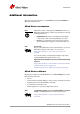
Introduction Additional information This section provides information on accessories and available software for Allied Vision GigE cameras. Allied Vision accessories Note Allied Vision offers a wide range of accessories for the use of Allied Vision GigE cameras and the easy integration in already existing applications. • • www Gigabit Ethernet accessories including standard GigE components as well as PoE capable GigE components. Lenses for corresponding sensor sizes and resolutions.
Introduction Third-party software In addition to the software provided by Allied Vision, there are numerous GigE Vision Standard compliant third-party software options available. In general, third-party software provides increased functionality such as image processing and video recording. Allied Vision’s Vimba SDK is based on the GenICam standard. GenICam-based third-party software automatically connects with Vimba's transport layers. Additionally, Vimba includes the Cognex Adapter for VisionPro.
Safety instructions Safety instructions This chapter describes safety instructions/cautions valid for Allied Vision GigE cameras and special safety instructions/cautions depending on the camera model used. General safety instructions Note • • • There are no switches or parts inside the camera that require adjustment. The guarantee becomes void upon opening the camera casing.
Safety instructions Sensor safety instructions Caution Sensor may be damaged Light intensity or exposure time exceeding the saturation of the sensor may damage the sensor irreparably. This may occur in the following situations: • • • Laser light hitting the sensor directly Bright light sources (e.g.
Safety instructions Safety instructions for board level cameras (only Manta and Prosilica GB) Note Caution-ESD Read the Manta / Prosilica GB Technical Manual and these safety instructions before use. Abuse or misapplication of the camera may result in limited warranty or cancellation of warranty. Board level cameras: ESD warnings • • • • • Board level cameras are delivered without housing. Handle the sensor board and main board with care. Do not bend the boards.
Safety instructions Caution Board level cameras: General warnings • • • • • • Caution Be sure that all power to your board level camera is switched off before mounting the sensor board or making connections to the camera. Do not connect or disconnect any cables during an electrical storm. Do not use your board level cameras during an electrical storm.
Getting started Getting started This chapter describes the components required for your camera system: GigE Vision camera Allied Vision offers the following GigE Vision camera families: – – – – – Bigeye G Goldeye G Mako Manta Prosilica GB – – – – – Prosilica GC Prosilica GE Prosilica GS Prosilica GT Prosilica GX This guide can be applied to all of these families. Follow the links below to learn more about GigE cameras from Allied Vision.
Getting started GigE Vision software Allied Vision provides several software packages that support our GigE Vision cameras. User can target the following operating systems and a variety of CPU architectures: • Windows, Linux (supported by both VIMBA and PvAPI SDKs) • QNX or OSX (supported by PvAPI SDK only) www VIMBA is Allied Vision's future-proof SDK for all current and upcoming Allied Vision cameras with GigE Vision, FireWire (IEEE 1394) and USB Vision interfaces.
Installing hardware Installing hardware This chapter describes the hardware installation and configuration of Gigabit Ethernet network cards (PC or laptop) for optimum system performance when using a GigE Vision camera. Installing Gigabit Ethernet network card GigE Vision cameras can operate on 10/100, or Gigabit speed Ethernet adapters. In order to take advantage of maximum camera frame rates, a Gigabit speed adapter is required.
Installing hardware Configuring Ethernet adapter 1. PC: Install the (second) Gigabit Ethernet network card in your host computer according to the instructions you got from your network card manufacturer. Laptop: Insert the Gigabit Ethernet ExpressCard into your laptop. 2. Cancel the Found new Hardware Wizard window that may appear when Windows detects your network card. Installing Ethernet adapter driver 3. Install the network card driver from your network card manufacturer.
Installing hardware Users can fix the adapter address to minimize the time required for a camera to be recognized by the host application. Systems that employ multiple Ethernet adapters connected to multiple cameras will also be required to fix the address of the Ethernet adapter.
Installing hardware [OSX] (PvAPI only) – System Preferences – Network – Select Ethernet, click Advanced – TCP/IP tab: Configure IPv4: Manually IPv4 Address: 169.254.100.1 Subnet Mask: 255.255.0.0 Router: Blank Figure 4: Interfaces file for static IP, Linux Ubuntu 10.04 Optimizing Ethernet adapter 5. The Ethernet adapter should be adjusted to improve system performance when using a GigE Vision camera. This performance is related to minimizing CPU usage and dropped or resent packets.
Installing hardware Adjusting camera packet size [Windows 7, Intel Gigabit CT] – Start, Control Panel – Hardware and Sound – Device Manager – Network Adapter – Right-click Adapter device name – Properties – Advanced tab – Settings: Jumbo Packet - Value: 9014 Bytes Figure 5: Setting jumbo packets Note The settings list in the advanced adapter settings may be different between different types/brands of Gigabit Ethernet network cards. Common expressions are Jumbo Frames or Jumbo Packet.
Installing hardware [OSX] (PvAPI only) – System Preferences – Network – Select Ethernet, click Advanced – Ethernet tab: Configure: Manually Speed: 1000baseT Duplex: full-duplex MTU: Jumbo (9000) Figure 6: Ethernet settings OSX Snow Leopard Adjusting buffers and moderation rate [Windows 7, Intel Gigabit CT] – Start, Control Panel – Hardware and Sound – Device Manager – Network Adapter – Right-click Adapter device name – Properties – Advanced tab – Performance Options – Settings: Interrupt Moderation Rate
Installing camera software Installing camera software This chapter presents instructions for software installation specific to Windows 7. Allied Vision GigE cameras can be operated under earlier versions of Windows including XP. Suggestions specific to Linux, QNX and OSX are also offered when applicable. Allied Vision offers two main SDKs for its GigE Vision cameras— VIMBA and PvAPI.
Installing camera software • • Select an installation level suitable for your needs. For first time users, installation level Camera Demonstration is recommended. Click Start. [Linux] Necessary runtime libraries for executing VIMBA Viewer are available with VIMBA SDK package. • VIMBA ships as a tarball. Uncompress the archive with the command tar -xf ./AVTVimba.tgz to a directory you have writing privileges for. This creates a directory named AVTVimba.
Installing camera software Installing GigE Sample Viewer First time users may want to install the GigE Sample Viewer which offers an excellent introduction to using the camera. Advanced users wishing to develop their own software should download PvAPI SDK. Source code for the GigE Sample Viewer is provided in the examples directory. A filter driver installation executable is also provided with the SDK. [Windows 7] • Go to install directory. • Click Allied_Vision_Technologies_GigE_Viewer_Installer.exe.
Starting the camera Starting the camera Power up A camera power adapter for each GigE camera is available from Allied Vision. Please consult the camera technical manual for connector definition and voltage specifications www Allied Vision Product literature http://www.alliedvision.com/en/support/technicaldocumentation Caution For Goldeye G, Prosilica, Mako, and Manta cameras: • • • Use only DC power supplies with insulated cases.
Using Allied Vision viewer applications Using Allied Vision viewer applications This chapter describes the use of two viewer applications offered by Allied Vision—VIMBA Viewer and GigE Sample Viewer. The viewer applications are used to stream live view images from the camera, adjust the camera parameters and test functionality. www VIMBA Viewer can be downloaded from the Allied Vision website: http://www.alliedvision.
Using Allied Vision viewer applications • Confirm that camera IP and Ethernet adapter are on the same subnet. For more information refer to Modifying camera IP address on page 35. 2. Select the desired camera from “Detected Cameras” list. 3. A new camera window appears, as shown in figure 10.
Using Allied Vision viewer applications If the images are too dark, point the camera directly at a light source to ensure images are not being dropped. If no images appear proceed to chapter Troubleshooting on page 47. Adjusting camera controls: Controller window The controller window, as shown in figure 10, is used to configure the camera frame rate, exposure time, color balance, imaging mode, strobe functionality, pixel format, and much more.
Using Allied Vision viewer applications Live histogram Start live view from the camera by selecting freerun button. Click the histogram icon in the viewer toolbar, shown left. This launches a live histogram. A histogram graphs number of pixels on the vertical axis and digital number value on the horizontal axis.
Using Allied Vision viewer applications Using GigE Sample Viewer This section describes main features of GigE Sample Viewer. Launching application Start the GigE Sample Viewer application. Wait for the camera to appear under Host. If a camera does not appear after some time, try the following: • Confirm the camera is powered. • Confirm the Ethernet cable is connected to the host PC. • Modify the Ethernet adapter and/or Camera IP such that they are on the same subnet.
Using Allied Vision viewer applications Adjusting camera controls Select the desired camera from the cameras window of the GigE Sample Viewer. Click the wrench icon to open controls window. The controls window is used to configure the camera frame rate, exposure time, color balance, imaging mode, strobe functionality, pixel format, and much more. Figure 15: GigE Sample Viewer controls window A detailed explanation of camera controls can be found in the GigE Camera and Driver Attributes document.
Using Allied Vision viewer applications Figure 16: GigE Sample Viewer information and histogram windows Event channel Select the desired camera from the cameras window of the GigE Sample Viewer. Click the film icon, shown left, to open the events window. This is a tool used to monitor in-camera events such as AcquisitionEnd, ExposureStart, ExposureEnd, etc. The factory default settings disable all event notifications. Use the camera controls to select which events to monitor.
Using Allied Vision viewer applications RS232 serial interface Select the desired camera from the cameras window of the GigE Sample Viewer. Click the serial icon, shown left, to open the serialIO window. This tool controls the camera’s RS232 port which communicates across the RXD and TXD pins on the camera IO port. All Allied Vision GigE cameras except Mako offer an RS232 port.
Using Allied Vision viewer applications Exporting camera settings Select the desired camera from the cameras window of the GigE Sample Viewer. Click the floppy disk icon, shown left. A file explorer window appears requesting a download location for the camera setup file. This file captures the current camera settings and creates a simple text file. This file can be uploaded to other cameras allowing both units to utilize the same camera settings.
Modifying camera IP address Modifying camera IP address Allied Vision GigE cameras support a number of IP addressing modes. Cameras shipped from the factory are configured to DHCP. If a DHCP server is not present, the camera uses the LLL / Auto IP configuration mode. Configuration Mode Description VIMBA: DHCP PvAPI: DHCP VIMBA: LLL PvAPI: Auto IP VIMBA: Persistent PvAPI: Fixed Obtain an IP address automatically using DHCP (Fallback to LLL/Auto IP) Obtain an IP address automatically (169.254.xxx.
Modifying camera IP address 4. A new window opens. In the controller window, go to GigE/Persistent and provide the desired values. 5. Go to GigE/Configuration/IP Configuration Mode. Set IP Configuration Mode = Persistent; and execute IP Configuration Apply command. Figure 23: Example - Setting fixed camera IP address in VIMBA Viewer (Windows OS) For PvAPI users [Windows 7] With the camera(s) connected to the host, run the IPConfig program.
Modifying camera IP address [Linux, OSX, QNX] With the camera(s) connect to the host, run the CLipConfig program included in the AVT GigE SDK/bin-pc directory. Source code is included in the examples. Figure 25: CLipConfig application command line options AVT GigE Cameras Installation Manual V1.1.
Using multiple cameras Using multiple cameras There is a number of different methods for configuring a multiple camera system. Most of these can be differentiated into two architectures: Single Ethernet port and Multiple Ethernet port. In order to determine which architecture is needed, start by calculating the amount of bandwidth required from the cameras based on the desired resolution, pixel format, frame rate and number of cameras.
Using multiple cameras www For more information on StreamBytesPerSecond and camera pixel format, see: PvAPI users: GigE Camera and Driver Attributes document VIMBA users: GigE Features Reference document Single Ethernet port Multiple cameras are connected to a switch. The switch is connected to a single Ethernet port. This is the simplest multiple camera installation. The cameras can be managed using Auto IP, no additional configuration on the switch is necessary.
Using multiple cameras Figure 27: GigE Sample Viewer window, controls window showing StreamBytesPerSecond feature Multiple Ethernet ports Each camera is connected directly to an Ethernet port. No switch is used. This configuration is more complex and requires the user to manage host and camera IP addressing; however, it allows each camera to use the entire Gigabit interface bandwidth.
Using multiple cameras The following steps are required to configure a multiple Ethernet port camera system: • Fix host adapter IP address • Fix camera IP address Note The host can be configured using multiple single port adapter cards, multiple dual port, quad port and so on. The same IP addressing model can be scaled to larger network configurations. Fix host adapter IP address – Refer to Modifying Ethernet adapter IP address on page 17.
Implementing link aggregation Implementing link aggregation The Prosilica GX series cameras offer two Gigabit Ethernet ports for image data transfer and control. Users can connect one or both ports on the Prosilica GX to Ethernet adapter ports on a host computer. The dual port approach requires the host computer to configure a Link Aggregate Group (LAG). A LAG configuration combines multiple Ethernet ports into a single data channel.
Implementing link aggregation Percentage of single port GigE bandwidth ~ 84%, LAG is not required to operate the GX1050 camera at 100 fps in Mono8. Example 2: GX1050C using YUV422 pixel format and outputting 100 fps Bandwidth usage = 1024 x 1024 x 2 (2 byte for YUV422) x 100 ~ 210 MBps Percentage of single port GigE bandwidth ~ 168%, LAG is required to operate the GX1050C at 100 fps using YUV422.
Implementing link aggregation – Select team type: Static Link Aggregation click Next Figure 35: Team wizard team type selection This configures the team and a new adapter appears in the Network Connections window. Note The newly formed team adapter can be managed using automatic IP configuration or fixed IP using instructions provided in Modifying Ethernet adapter IP address on page 17. [Linux] Link Aggregation is referred to as bonding in Linux. The following instructions are for Ubuntu Linux 10.
Implementing link aggregation [OSX] (PvAPI only) www For full installation instructions on OSX, see: http://docs.info.apple.com/ article.html?path=ServerAdmin/10.6/en/ asa7873dc0.html Note These instructions are for OSX server, but apply to OSX also. – – – – – System Preferences Network Select Ethernet, click gear icon, Manage Virtual Interfaces Click the Add (+) button, and select New Link Aggregate Select the ports to bond from the list, click Create, Done.
Multicasting configuration Multicasting configuration Multicasting allows multiple hosts on the same network to receive camera image data. One host acts as master/controller, and the others act as monitor. Most network hardware only supports multicasting at maximum packet size 1500. www For enabling/disabling multicasting, see: PvAPI users: GigE Camera and Driver Attributes document VIMBA users: GigE Features Reference document [Windows] Ensure camera packet size is 1500.
Troubleshooting Troubleshooting Is the camera getting power? The RJ45 Ethernet connector on the back for the camera contains LEDs, one of which illuminates when the camera is powered. If unlit, check the power adapter. If possible, test the adapter with a working camera to verify its operation. If using a custom power adapter, be sure the adapter and wire gauge is rated to 200–500 mA.
Troubleshooting If you are still having problems, type: ipconfig /all in a command prompt [windows]; ifconfig -a in terminal [Linux, OSX, QNX]. Send resulting screenshot to support@alliedvision.com. Figure 39: ipconfig /all. Windows AVT GigE Cameras Installation Manual V1.1.
Troubleshooting Is the camera listed in Viewer but can't acquire images? Reset your camera settings to factory default. VIMBA Viewer GigE Sample Viewer In controller window, set UserSetDefaultSelector = Default, and click the UserSetLoad button. In controls window, set ConfigFileIndex = Factory, click ConfigFileLoad button. While streaming, check the camera Stats. StatFramesDelivered / StatPacketsReceived = 0 • Likely a firewall is blocking incoming traffic.
Troubleshooting How to minimize/eliminate dropped packets? • • Check the Gigabit Ethernet cable. A damaged cable often causes the host to switch to 10/100 speed mode. Use one of the NICs recommended in our hardware selection guide. www • • A list of Allied Vision recommended Ethernet adapters is available on the website. http://www.alliedvision.com/fileadmin/content/ documents/products/cameras/various/appnote/ Hardware_Selection_for_Allied_Vision_GigE_Cameras.
Troubleshooting • Linux only: Run as root, allowing the OS to boost the priority of the Allied Vision driver thread, and the driver to bind directly to the NIC adapter.
Additional references Additional references Product webpage http://www.alliedvision.com/en/products/cameras Product manuals http://www.alliedvision.com/en/support/technical-documentation VIMBA SDK http://www.alliedvision.com/en/products/software PvAPI SDK - (Under Legacy Software) http://www.alliedvision.com/en/support/software-downloads Knowledge base http://www.alliedvision.com/en/support/technical-papers-knowledge-base Case studies http://www.alliedvision.com/en/applications Firmware http://www.
Index Index A Allied Vision accessories .............................. 8 Auto IP configuration ........................... 35, 47 B Board level cameras Dirty environments.............................. 13 General warnings ................................ 13 Loading ............................................ 13 Safety instructions .............................. 12 C Camera Power up ...................................... 25 Category 6..................................... 16, 25, 47 Changing filters ......
Index P Packet size ...............................19, 20, 46, 49 Performance Options ................................. 15 PoE.....................................................8, 25 Power DC.................................................... 25 PvAPI SDK .......................................... 15, 22 R Receive buffers .............................. 19, 21, 50 Receive Descriptors................................... 15 RS232 ....................................................