Allied Vision Prosilica GE Technical Manual GigE Vision Cameras V2.1.
Legal notice For customers in the U.S.A. This equipment has been tested and found to comply with the limits for a Class A digital device, pursuant to Part 15 of the FCC Rules. These limits are designed to provide reasonable protection against harmful interference when the equipment is operated in a residential environment.
Contents Contacting Allied Vision .................................................................................. 5 Introduction ............................................................................................................ 6 Document history............................................................................................................ 6 Manual conventions......................................................................................................... 8 Styles .........
Camera interfaces .............................................................................................41 Status LEDs .................................................................................................................. 41 Gigabit Ethernet port ..................................................................................................... 42 Camera I/O connector pin assignment ............................................................................... 43 I/O definition .......
Contacting Allied Vision Contacting Allied Vision Info • Technical information: http://www.alliedvision.com • Support: support@alliedvision.com Allied Vision Technologies GmbH (Headquarters) Taschenweg 2a 07646 Stadtroda, Germany Tel.: +49 36428-677-0 Fax: +49 36428-677-28 e-mail: info@alliedvision.com Allied Vision Technologies Canada Inc. 101-3750 North Fraser Way Burnaby, BC, V5J 5E9, Canada Tel.: +1 604-875-8855 Fax: +1 604-875-8856 e-mail: info@alliedvision.com Allied Vision Technologies Inc.
Introduction Introduction This Prosilica GE Technical Manual describes in depth the technical specifications of the Prosilica GE camera family including dimensions, feature overview, I/O definition, trigger timing waveforms, and frame rate performance. For information on software installation read the GigE Installation Manual. For detailed information on camera features and controls specific to the Prosilica GE refer to the GigE Features Reference and GigE Camera and Driver Attributes documents.
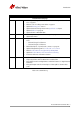
Introduction Version Date Remarks continued from last page V2.0.2 2013-Oct-02 • • • • • • Added optical flange focal distance and maximum lens protrusion information on page 37 Added a note on locking screw cables on page 41 Updated Cleaning optics section Updated vertical binning values in the Specifications chapter Updated Table 12 on page 31 Updated links for AVT PvAPI SDK V2.0.3 2013-Nov-26 • • Added chapter Description of the data path on page 58 Updated the Index V2.0.
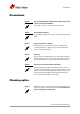
Introduction Manual conventions To give this manual an easily understandable layout and to emphasize important information, the following typographical styles and symbols are used: Styles Style Function Example Bold Programs, inputs, or highlighting important information bold Courier Code listings etc. Input Upper case Register REGISTER Italics Modes, fields Mode Parentheses and/or blue Links (Link) Table 2: Styles Symbols Note This symbol highlights important information.
Introduction Precautions Caution Do not disassemble the camera housing. Warranty is void if camera has been disassembled. This camera contains sensitive internal components. Caution Keep shipping material. Poor packaging of the product may cause damage during shipping. Caution Verify all external connections. Verify all external connections in terms of voltage levels, power requirements, voltage polarity, and signal integrity prior to powering the device. Caution Cleaning.
Introduction Caution Do not touch any optics with fingers. Oil from fingers can damage fragile optical coatings. Identifying debris Debris on the image sensor or optical components appears as a darkened area or smudge on a camera image. Do not confuse this with a pixel defect which appears as a distinct point. Locating debris First determine whether the debris is on the sensor glass, IR filter (if used), or lens.
Introduction Caution Do not exceed 6 bar (90 psi). If using canned air, approximately ~ 4.8 bar (70 psi) when full, do not shake or tilt the can, as extreme changes in temperature due to sudden cold air can crack the optic glass. View a live image with the camera after blowing. If debris is still present, repeat the process until it is determined that the particulate cannot be dislodged. If this is the case, proceed to the contact cleaning technique.
Conformity Conformity Allied Vision Technologies declares under its sole responsibility that all standard cameras of the Prosilica GE family to which this declaration relates are in conformity with the following standard(s) or other normative document(s): • CE, following the provisions of 2004/108/EG directive • FCC Part 15 Class A • RoHS (2011/65/EU) We declare, under our sole responsibility, that the previously described Prosilica GE cameras conform to the directives of the CE.
Specifications Specifications Prosilica GE680/680C Feature Specification Resolution Sensor Type Sensor size Cell size Lens mount Max frame rate at full resolution A/D On-board FIFO Bit depth 640 x 480 OnSemi KAI-0340 CCD Progressive Type 1/3 7.4 μm C (adjustable) 205 fps 12 bit 32 MB 8/12 Mono formats GE680: Mono8, Mono12, Mono12Packed GE680C: Mono8 BayerGR8, BayerGR12, BayerGR12Packed, RGB8Packed, BGR8Packed, RGBA8Packed, BGRA8Packed, RGB12Packed, YUV411Packed 25 μs to 53.
Specifications 60% Measured with clear cover glass Quantum Efficiency 50% 40% 30% 20% 10% 0% 300 400 500 600 700 Wavelength [nm] 800 900 1000 1100 Figure 1: Prosilica GE680 monochrome spectral response Red Green Blue 45% Measured with clear cover glass Quantum Efficiency 40% 35% 30% 25% 20% 15% 10% 5% 0% 300 400 500 600 700 Wavelength [nm] 800 900 1000 1100 Figure 2: Prosilica GE680C color spectral response (without IR cut filter) Prosilica GE Technical Manual V2.1.
Specifications Prosilica GE1050/1050C Feature Specification Resolution 1024 x 1024 Sensor OnSemi KAI-01050 Type CCD Progressive Sensor size Type 1/2 Cell size 5.5 μm Lens mount C (adjustable) Max frame rate at full resolution 59 fps A/D 12 bit On-board FIFO 32 MB Bit depth 8/12 Mono formats Exposure control GE1050: Mono8, Mono12, Mono12Packed GE1050C: Mono8 BayerGR8, BayerGR12, BayerGR12Packed, RGB8Packed, BGR8Packed, RGBA8Packed, BGRA8Packed, RGB12Packed, YUV411Packed 10 μs to 53.
Specifications 60% Measured with AR coated cover glass Quantum Efficiency 50% 40% 30% 20% 10% 0% 350 400 450 500 550 600 650 700 750 800 850 900 950 1000 1050 1100 Wavelength [nm] Figure 3: Prosilica GE1050 monochrome spectral response Red 45% Green Blue Measured with AR coated cover glass Quantum Efficiency 40% 35% 30% 25% 20% 15% 10% 5% 0% 400 500 600 700 800 Wavelength [nm] 900 1000 1100 Figure 4: Prosilica GE1050C color spectral response (without IR cut filter) Prosilica GE Technical M
Specifications Prosilica GE1650/1650C Feature Resolution Specification 1600 x 1200 Sensor OnSemi KAI-2020 Type CCD Progressive Sensor size 1 inch Cell size 7.4 μm Lens mount C (adjustable) Max frame rate at full resolution 32 fps A/D 12 bit On-board FIFO 32 MB Bit depth 8/12 Mono formats Exposure control GE1650: Mono8, Mono12, Mono12Packed GE1650C: Mono8 BayerGR8, BayerGR12, BayerGR12Packed, RGB8Packed, BGR8Packed, RGBA8Packed, BGRA8Packed, RGB12Packed, YUV411Packed 50 μs to 53.
Specifications 60% Quantum Efficiency 50% 40% 30% 20% 10% 0% 250 400 550 700 Wavelength [nm] 850 1000 1150 Figure 5: Prosilica GE1650 monochrome spectral response Red 45% Green Blue Quantum Efficiency 40% 35% 30% 25% 20% 15% 10% 5% 0% 400 450 500 550 600 650 700 750 Wavelength [nm] 800 850 900 950 1000 Figure 6: Prosilica GE1650C color spectral response (without IR cut filter) Prosilica GE Technical Manual V2.1.
Specifications Prosilica GE1660/1660C Feature Resolution Specification 1600 x 1200 Sensor OnSemi KAI-2050 Type CCD Progressive Sensor size 2/3 inch Cell size 5.5 μm Lens mount C (adjustable) Max frame rate at full resolution 34.6 fps A/D 12 bit On-board FIFO 32 MB Bit depth 8/12 Mono formats Exposure control GE1660: Mono8, Mono12, Mono12Packed GE1660C: Mono8 BayerGR8, BayerGR12, BayerGR12Packed, RGB8Packed, BGR8Packed, RGBA8Packed, BGRA8Packed, RGB12Packed, YUV411Packed 10 μs to 53.
Specifications 60% Measured with AR coated cover glass Quantum Efficiency 50% 40% 30% 20% 10% 0% 350 450 550 650 750 850 Wavelength [nm] 950 1050 1150 Figure 7: Prosilica GE1660 monochrome spectral response Red 45% Green Blue Measured with AR coated cover glass 40% Quantum Efficiency 35% 30% 25% 20% 15% 10% 5% 0% 400 500 600 700 800 Wavelength [nm] 900 1000 1100 Figure 8: Prosilica GE1660C color spectral response (without IR cut filter) Prosilica GE Technical Manual V2.1.
Specifications Prosilica GE1900/1900C Feature Resolution Specification 1920 x 1080 Sensor OnSemi KAI-2093 Type CCD Progressive Sensor size 1 inch Cell size 7.4 μm Lens mount C (adjustable) Max frame rate at full resolution 30 fps A/D 12 bit On-board FIFO 32 MB Bit depth 8/12 Mono formats Exposure control GE1900: Mono8, Mono12, Mono12Packed GE1900C: Mono8 BayerGR8, BayerGR12, BayerGR12Packed, RGB8Packed, BGR8Packed, RGBA8Packed, BGRA8Packed, RGB12Packed, YUV411Packed 50 μs to 53.
Specifications Without cover glass With cover glass Without cover glass without microlens 45% Quantum Efficiency 40% 35% 30% 25% 20% 15% 10% 5% 0% 300 400 500 600 700 Wavelength [nm] 800 900 1000 Figure 9: Prosilica GE1900 monochrome spectral response Red 40% Green Blue Measured with clear cover glass Quantum Efficiency 35% 30% 25% 20% 15% 10% 5% 0% 400 500 600 700 Wavelength [nm] 800 900 1000 Figure 10: Prosilica GE1900C color spectral response (without IR cut filter) Prosilica G
Specifications Prosilica GE1910/1910C Feature Resolution Specification 1920 x 1080 Sensor OnSemi KAI-02150 Type CCD Progressive Sensor size 2/3 inch Cell size 5.5 μm Lens mount C (adjustable) Max frame rate at full resolution 32 fps A/D 12 bit On-board FIFO 32 MB Bit depth 8/12 Mono formats Exposure control GE1910: Mono8, Mono12, Mono12Packed GE1910C: Mono8 BayerGR8, BayerGR12, BayerGR12Packed, RGB8Packed, BGR8Packed, RGBA8Packed, BGRA8Packed, RGB12Packed, YUV411Packed 10 μs to 53.
Specifications 50% Measured with AR coated cover glass 45% 40% Quantum Efficiency 35% 30% 25% 20% 15% 10% 5% 0% 350 450 550 650 750 Wavelength [nm] 850 950 1050 Figure 11: Prosilica GE1910 monochrome spectral response Red 40% Green Blue Measured with AR coated cover glass Quantum Efficiency 35% 30% 25% 20% 15% 10% 5% 0% 375 475 575 675 775 Wavelength [nm] 875 975 1075 Figure 12: Prosilica GE1910C color spectral response (without IR cut filter) Prosilica GE Technical Manual V2.1.
Specifications Prosilica GE2040/2040C Feature Resolution Specification 2040 x 2048 Sensor OnSemi KAI- 04022 Type CCD Progressive Sensor size 1.2 inch Cell size 7.4 μm Lens mount C (adjustable) / F Max frame rate at full resolution 15 fps A/D 12 bit On-board FIFO 32 MB Bit depth 8/12 Mono formats Exposure control GE2040: Mono8, Mono12, Mono12Packed GE2040C: Mono8 BayerGR8, BayerGR12, BayerGR12Packed, RGB8Packed, BGR8Packed, RGBA8Packed, BGRA8Packed, RGB12Packed, YUV411Packed 75 μs to 53.
Specifications 60% Measured with glass Quantum Efficiency 50% 40% 30% 20% 10% 0% 350 400 450 500 550 600 650 700 750 Wavelength [nm] 800 850 900 950 1000 Figure 13: Prosilica GE2040 monochrome spectral response Red 50% Green Blue Measured with glass 45% Quantum Efficiency 40% 35% 30% 25% 20% 15% 10% 5% 0% 400 500 600 700 Wavelength [nm] 800 900 1000 Figure 14: Prosilica GE2040C color spectral response (without IR cut filter) Prosilica GE Technical Manual V2.1.
Specifications Prosilica GE4000/4000C Feature Specification Resolution 4008 x 2672 Sensor OnSemi KAI-11002 Type CCD Progressive Sensor size 35 mm Cell size 9 μm Lens mount F Max frame rate at full resolution 5 fps A/D 12 bit On-board FIFO 32 MB Bit depth 8/12 Mono formats GE4000: Mono8, Mono12, Mono12Packed Color formats BayerGR8, BayerGR12, BayerGR12Packed Exposure control 140 μs to 68.
Specifications 60% Quantum Efficiency 50% 40% 30% 20% 10% 0% 300 400 500 600 700 Wavelength [nm] 800 900 1000 Figure 15: Prosilica GE4000 monochrome spectral response Red Green Blue 45% Quantum Efficiency 40% 35% 30% 25% 20% 15% 10% 5% 0% 400 500 600 700 Wavelength [nm] 800 900 1000 Figure 16: Prosilica GE4000C color spectral response (without IR cut filter) Prosilica GE Technical Manual V2.1.
Specifications Prosilica GE4900/4900C Feature Specification Resolution 4872 x 3248 Sensor OnSemi KAI-16000 Type CCD Progressive Sensor size 35 mm Cell size 7.4 μm Lens mount F Max frame rate at full resolution 3 fps A/D 12 bit On-board FIFO 32 MB Bit depth 8/12 Mono formats GE4900: Mono8, Mono12, Mono12Packed Color formats BayerGR8, BayerGR12, BayerGR12Packed Exposure control 625 μs to 68.
Specifications 50% Measured with AR coated cover glass 45% Quantum Efficiency 40% 35% 30% 25% 20% 15% 10% 5% 0% 350 500 650 800 Wavelength [nm] 950 1100 Figure 17: Prosilica GE4900 monochrome spectral response Red 45% Green Measured without AR coated cover glass 40% Quantum Efficiency Blue 35% 30% 25% 20% 15% 10% 5% 0% 400 500 600 700 800 Wavelength [nm] 900 1000 1100 Figure 18: Prosilica GE4900C color spectral response (without IR cut filter) Prosilica GE Technical Manual V2.1.
Camera attribute highlights Camera attribute highlights Allied Vision cameras support a number of standard and extended features. The table below identifies a selection of interesting capabilities of the Prosilica GE camera family.
Filters Filters All Prosilica GE color models are equipped with an infrared block filter (IR filter). This filter is employed to prevent infrared wavelength photons from passing to the sensor. In the absence of IR filter, images are dominated by red and incapable of being properly color balanced. Monochrome cameras do not employ an IR filter. The figure below shows the filter transmission response for the IRC30 filter employed in the Prosilica GE cameras.
Camera dimensions Camera dimensions Prosilica GE C-Mount (adjustable): GE680/680C 26 26 M3x3 (2x) 20.2* 79.6* 64 50 M3x3 (4x) *Nominal value. Add 0.3mm for GE680C. 51.6 39.4 Figure 20: Prosilica GE680 adjustable C-Mount mechanical dimensions Prosilica GE Technical Manual V2.1.
Camera dimensions Prosilica GE C-Mount (adjustable) GE1050/1050C, GE1650/1650C, GE1660/1660C, GE1900/1900C, GE1910/ 1910C, GE2040/2040C 35 M3x4 (4x) 40 26 26 M3x3 (2x) 13.9* 80.4* 64 57 M3x3 (4x) *Nominal value. Add 0.3mm for color cameras. 51.6 39.4 Figure 21: Prosilica GE adjustable C-Mount models mechanical dimensions Prosilica GE Technical Manual V2.1.
Camera dimensions Prosilica GE F-Mount: GE2040/2040C 59.7 26 M3x3 (2x) 26 42.3* 64 57 M3x3 (4x) *Nominal value. Add 0.3mm for color cameras. 51.6 39.4 Figure 22: Prosilica GE F-Mount mechanical dimensions Prosilica GE Technical Manual V2.1.
Camera dimensions Prosilica GE large format F-Mount: GE4000/ 4000C, GE4900/4900C 59.7 49* 109.7* 50 TYP M3x3 (16x) 26 TYP *Nominal value. Add 0.3mm for color cameras. 66 66 Figure 23: Prosilica GE large format F-Mount mechanical dimensions Prosilica GE Technical Manual V2.1.
Camera dimensions Tripod adapter A Prosilica GE camera can be mounted on a camera tripod by using a mounting plate P/N 02-5000A. The same mounting plate can be used for all models within the GE camera family. Note Prosilica GE tripod mount is available for purchase from Allied Vision. 4 P/N: 02-5000A 6 20 12.8 6.5 0.5 R1.6 8 PLCS TYP. 32.5 20 0.5 12 6 10 62.5 6 THRU 14 28 3.4 THRU 6 PLCS TYP.
Camera dimensions C-Mount flange focal distance Flange focal distance is the optical distance from the mounting flange to image sensor die. Prosilica GE C-Mount cameras are optically calibrated to a standard 17.526 mm optical flange focal distance, with a ±10 μm tolerance. www Prosilica GE cameras are shipped with adjustable C-Mount. The camera can also be built with a CS-Mount with a standard 12.50 mm optical flange focal distance and a ± 10 μm tolerance.
Camera dimensions Image to infinity Use a C-Mount compatible lens that allows an infinity focus. Set the lens to infinity and image a distant object—10 to 15 m should suffice. Make sure the lens is firmly threaded onto the C-Mount ring. Rotate the lens and C-Mount ring until the image is focused. Carefully tighten the locking ring and recheck focus.
Camera dimensions F-Mount flange focal distance Flange focal distance is the optical distance from the mounting flange to image sensor die. Prosilica GE F-Mount cameras are optically calibrated to a standard 46.5 mm optical flange focal distance. Adjustment of F-Mount The F-Mount is adjusted at the factory and should not require adjusting. If for some reason, the lens mount requires adjustment, use the following method.
Camera interfaces Camera interfaces This chapter provides information on Gigabit Ethernet port, inputs and outputs, and trigger features. www Accessories: Please contact Allied Vision sales representative or your local Allied Vision dealer for information on accessories: http://www.alliedvision.com/en/about-us/where-weare.
Camera interfaces Gigabit Ethernet port The Gigabit Ethernet port conforms to the IEEE 802.3 1000BASE-T standard for Gigabit Ethernet over copper. Allied Vision recommends using Category 6 or higher compatible cabling and connectors for best performance. www Note Note GigE Installation Manual offers detailed instructions for using Prosilica GE cameras. http://www.alliedvision.com/fileadmin/content/documents/ products/cameras/various/installation-manual/ GigE_Installation_Manual.
Camera interfaces Camera I/O connector pin assignment 8 9 1 10 2 7 12 11 3 6 4 5 Pin Signal Direction Level Description 1 In 1 In TTL max. 5 V 2 Out 2 Out TTL max. 5 V 3 Out 3 Out TTL max.
Camera interfaces I/O definition Camera power The Prosilica GE camera family supports a wide input power voltage range. The camera will not power in reverse polarity. Exceeding the voltage range specified below will damage the camera. Caution 5–24 V. 12 V nominal. Note Prosilica GE has a built-in power barrel connector (Switchcraft PC712a). A 12 V power adapter with barrel connection plug (Switchcraft 760K)is available for purchase from Allied Vision: • • P/N 02-8005C North America Supply.
Camera interfaces Caution Do not exceed 5.5 V on In 1. The Mini-SMB trigger input is internally connected to the In 1 of the general purpose I/O port. The Mini-SMB port on the camera uses an Amphenol 903406J-51R connector. A suitable mating cable connector is Amp 413985-3 which can be used with RG174 coaxial cable. Note SMB to SMB cables is available for purchase from Allied Vision with various lengths.
Camera interfaces Out 2 and Out 3 Out 2 and Out 3 can be configured to active high or active low.
Camera interfaces Camera I/O connector internal circuit diagram 9 8 1 2 10 12 7 1 2 3 4 5 6 7 8 9 10 11 12 11 6 3 4 5 TRIGGER INPUT SYNC OUT 2 SYNC OUT 3 RS-232 RXD RS-232 TXD 2 18 16 1Y1 1A1 4 1Y2 1A2 14 6 1Y3 1A3 12 8 1Y4 1A4 9 7 5 3 2Y1 2Y2 2Y3 2Y4 HIROSE HR10A-10R-12SB AS SEEN FROM CAMERA REAR VIEW CAMERA INTERNAL CIRCUIT 2A1 2A2 2A3 2A4 11 13 15 17 1OE 2OE VCC GND 1 19 20 10 ISO+5V ISO+5V VDD -3.
Camera interfaces Camera I/O connector external circuit example CABLE SIDE 1 2 3 4 5 6 7 8 9 10 11 12 TRIGGER INPUT OUT 2 OUT 3 IN 1 (5 V TTL DRIVER) OUT 2 (5 V TTL RECEIVER) OUT 3 (5 V TTL RECEIVER) 9 1 2 8 10 11 3 12 4 7 6 5 HIROSE HR10A-10P-12P Figure 31: Prosilica GE external circuit The trigger circuit is connected to a Texas Instruments SN74ACT244PWR buffer/ driver inside the camera. Caution Input: Incoming trigger must be able to source 10 μA. Output: Sync output current is 24 mA.
Camera interfaces In 1, Out 1 external circuit example RG-174 COAX CABLE MINI-SMB TRIGGER INPUT IN 1 (5 V TTL DRIVER) IN RG-174 COAX CABLE OUT 1 OUT 1 (5 V TTL RECEIVER) MINI-SMB OUT Figure 32: Prosilica GE In 1, Out 1 external circuit The trigger circuit is connected to a Texas Instruments SN74ACT244PWR buffer/ driver inside the camera. Note that the trigger input signal is not terminated to match the cable impedance. Caution Input: The required trigger input current is less than 10 μA.
Camera interfaces Trigger timing diagram Readout time Trigger latency Tpd Registered exposure time Exposure start delay User trigger Note: Jitter at the beginning of an exposure has no effect on the length of exposure.
Camera interfaces Term Definition Trigger ready Indicates to the user that the camera will accept the next trigger Registered exposure time Exposure time value currently stored in the camera memory Exposure start delay Registered exposure time subtracted from the readout time and indicates when the next exposure cycle can begin such that the exposure will end after the current readout Interline time Time between sensor row readout cycles Imaging High when the camera image sensor is either exposing
Firmware update Firmware update Firmware updates are carried out via the GigE connection. Allied Vision provides an application for all Prosilica GE cameras that loads firmware to the camera using a simple interface. New feature introductions and product improvements motivate new firmware releases. All users are encouraged to use the newest firmware available and complete the firmware update if necessary. www Download the latest GigE firmware loader from the Allied Vision website: http://www.
Resolution and ROI frame rates Resolution and ROI frame rates This section provides the performance information which identifies the impact of reducing the region of interest on the camera’s maximum frame rate. Note • • • • Frame rate data was generated using StreamBytesPerSecond = 124 MB/s and an 8 bit pixel format such as Mono8, BayerGR8, or BayerRG8. Frame rates may be lower if using network hardware incapable of 124 MB/s.
Resolution and ROI frame rates Prosilica GE1050 1 Frame rate = ------------------------------------------------------------------------11.72 μs Height + 4948.66 μs 205 Frame Rate [fps] 180 155 130 105 80 55 0 150 300 450 600 Height [pixels] 750 900 1050 Figure 35: Frame rate vs. height for Prosilica GE1050 Prosilica GE1650 1 Frame rate = ------------------------------------------------------------------------17.61 μs Height + 10119.
Resolution and ROI frame rates Prosilica GE1660 Frame Rate [fps] 1 Frame rate = ------------------------------------------------------------------------17.99 μs Height + 7398.16 μs 140 130 120 110 100 90 80 70 60 50 40 30 0 200 400 600 Height [pixels] 800 1000 1200 Figure 37: Frame rate vs. height for Prosilica GE1660 Prosilica GE1900 1 Frame rate = ---------------------------------------------------------------------------18.31 μs Height + 13114.
Resolution and ROI frame rates Prosilica GE1910 Frame Rate [fps] 1 Frame rate = ------------------------------------------------------------------------21.35 μs Height + 7526.47 μs 140 130 120 110 100 90 80 70 60 50 40 30 0 100 200 300 400 500 600 700 Height [pixels] 800 900 1000 1100 Figure 39: Frame rate vs. height for Prosilica GE1910 Prosilica GE2040 1 Frame rate = ---------------------------------------------------------------------------15.63 μs Height + 33773.
Resolution and ROI frame rates Prosilica GE4000 1 Frame rate = ---------------------------------------------------------------------------52.45 μs Height + 56713.22 μs 19 Frame Rate [fps] 17 15 13 11 9 7 5 0 300 600 900 1200 1500 Height [pixels] 1800 2100 2400 2700 Figure 41: Frame rate vs. height for Prosilica GE4000 Prosilica GE4900 1 Frame rate = ---------------------------------------------------------------------------70.73 μs Height + 69676.
Resolution and ROI frame rates Prosilica GE model comparison GE1050 GE1650 GE1660 GE1900 GE1910 210 Frame Rate [fps] 180 150 120 90 60 30 0 200 400 600 800 1000 1200 Height [pixels] Figure 43: Maximum frame rate vs. height for select Prosilica GE camera models GE4000 GE4900 18 Frame Rate [fps] 15 12 9 6 3 0 300 600 900 1200 1500 1800 2100 2400 2700 3000 3300 Height [pixels] Figure 44: Maximum frame rate vs.
Camera data path Camera data path The following diagrams illustrate the data flow and the bit resolution of image data. The individual blocks are described in more detail in the GigE Features Reference document. Prosilica GE: monochrome cameras Sensor Vertical binning / Analog Vertical ROI Offset‡ Gain Analog ADC Analog Analog 12 bit Camera control HIROSE I/O RS232 Gigabit Frame Ethernet 12 bit memory interface 12 bit GigE ‡ Horizontal binning 12 bit Horizontal ROI Factory calibrated.
Additional references Additional references Prosilica GE webpage http://www.alliedvision.com/en/products/cameras Prosilica GE Documentation http://www.alliedvision.com/en/support/technical-documentation/ prosilica-ge-documentation VIMBA SDK http://www.alliedvision.com/en/products/software PvAPI SDK- (Under Legacy Software) http://www.alliedvision.com/en/support/software-downloads Knowledge base http://www.alliedvision.com/en/support/technical-papers-knowledge-base Case studies http://www.alliedvision.
Index Index A L Adjusting C-Mount ............................................ 38 F-Mount ............................................ 40 Legal notice .............................................. 2 Lens protrusion........................................ 39 Logic trigger (definition) ........................... 50 B M Block diagram Prosilica GE color cameras..................... 59 Prosilica GE monochrome cameras .......... 59 Mechanical dimensions Prosilica GE C-Mount............................
Index Prosilica GE1050 ................................. 16 Prosilica GE1050C ............................... 16 Prosilica GE1650 ................................. 18 Prosilica GE1650C ............................... 18 Prosilica GE1660 ................................. 20 Prosilica GE1660C ............................... 20 Prosilica GE1900 ................................. 22 Prosilica GE1900C ............................... 22 Prosilica GE1910 ................................. 24 Prosilica GE1910C .....