
Instruction manual

Prosilica GS Technical Manual V2.0.5
25
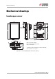
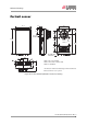
Mechanical drawings
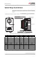
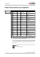
Optical flange focal distance
Optical flange focal distance is the optical distance from the mounting flange to
the image sensor die (see figure 12). Optical flange focal distance can be calcu-
lated as:
Figure 12: Cross section of typical Prosilica GS assembly with C-Mount
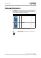
Camera Sensor orientation Lens protrusion
[mm]
IR cut filter*
[mm]
Sensor window
[mm]
Nominal flange focal
distance [mm]
GC650 Portrait 13.64 0.00 0.75 17.78
GS650 Landscape 13.64 0.00 0.75 17.78
GC650C Landscape 8.95 1.00 0.75 18.11
GC650C Portrait 9.27 1.00 0.75 18.11
GC660 Landscape 13.64 0.00 0.75 17.78
GC660C Landscape 8.41 1.00 0.75 18.11
GC1380 Landscape 13.64 0.00 0.75 17.78
GC1380 Portrait 13.64 0.00 0.75 17.78
GC1380C Landscape 9.00 1.00 0.75 18.11
GC1380C Portrait 9.32 1.00 0.75 18.11
GC2450 Landscape 13.64 0.00 0.50 17.69
GC2450C Landscape 8.29 1.00 0.50 18.03
* Only color camera models are equipped with IR cut filter.
Table 9: Flange focal distance and maximum lens protrusion for Prosilica GS cameras with C-Mount
Optical flange focal distance Flange focal distance
IR cut filter thickness Sensor window thickness+
3
-------------------------------------------------------------------------------------------------------------
–
Flange focal distance
Max. lens protrusion
IR cut filter thickness Sensor window thickness
A
A
Section A-A
Image sensor die