
Instruction manual


Table Of Contents
- Contacting Allied Vision
- Introduction
- Camera cleaning instructions
- About Mako GigE cameras
- Conformity
- Specifications
- Camera smart features
- Filter and lenses
- Camera dimensions
- Camera interfaces
- Description of the data path
- Resolution and ROI frame rates
- Appendix
Mako Technical Manual V3.0.0
48
Camera interfaces
For all Mako models:
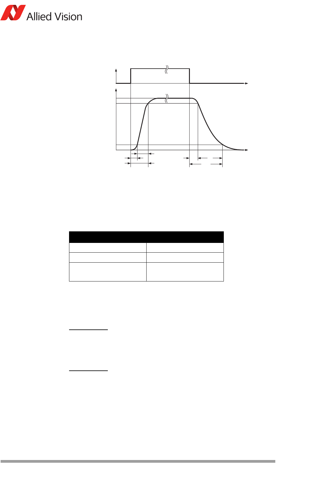
Test conditions
Output: external 2.4 k resistor to GND, Camera Out Power set to 12 V.
Figure 38: Mako output switching times
Parameter and value
t
d
1 µs t
s
26 µs
t
r
1 µs t
f
21 µs
t
on
= t
d
+ t
r
2 µs t
off
= t
s
+ t
f
47 µs
(t
off
can deviate by 5 µs)
Table 25: Parameters for Mako
Note
Higher external values increase the times in the table above.
Note
We recommend to trigger on the rising edge. This guarantees a
fastest possible reaction time.
I
F
0
I
C
100%
90%
10%
t
t
0
delay time
rise time
turn-on time
storage time
fall time
turn-o time
Optocoup
ler input (internal)
Optocoupler output (extern
al)
t
o
(= t
s
+ t
f
)
t
d
t
r
t
on
(= t
d
+ t
r
)
t
s
t
f
t
d
t
on
t
r
t
s
t
f
t
o