
Instruction manual


Table Of Contents
- Contacting Allied Vision
- Introduction
- Camera cleaning instructions
- About Mako GigE cameras
- Conformity
- Specifications
- Camera smart features
- Filter and lenses
- Camera dimensions
- Camera interfaces
- Description of the data path
- Resolution and ROI frame rates
- Appendix
Mako Technical Manual V3.0.0
46
Camera interfaces
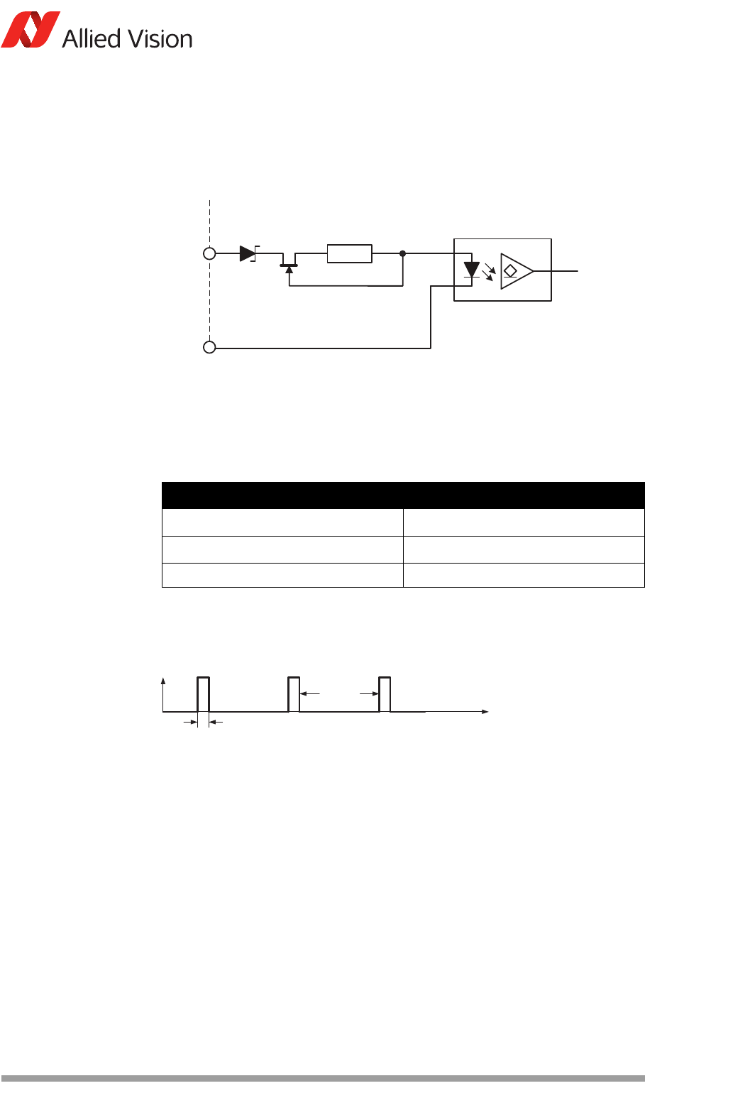
Mako input description
Mako input block diagram
The input can be connected directly to the system for voltages up to 24 V DC. An
external resistor is not necessary.
Mako delay and minimum pulse width
The minimum pulse width for all Mako cameras is:
Test conditions
The input signal was driven with 3.3 V and no external additional series resistor.
Figure 34: Mako input block diagram
Parameter Value
U
in
(low) 0–1.0 V
U
in
(high) 3–24 V
Current (constant-current source) 3–4 mA
Table 24: Mako input parameters
Figure 35: Mako minimum pulse width
In1
Camera In GND
External Internal
180R
I
F
0
t
44 s
6 s 20 kHz