
Instruction manual


Table Of Contents
- Contacting Allied Vision
- Introduction
- Camera cleaning instructions
- About Mako GigE cameras
- Conformity
- Specifications
- Camera smart features
- Filter and lenses
- Camera dimensions
- Camera interfaces
- Description of the data path
- Resolution and ROI frame rates
- Appendix
Mako Technical Manual V3.0.0
44
Camera interfaces
Camera interfaces
This chapter describes the Gigabit Ethernet port, inputs and outputs, and trig-
ger features.
Status LEDs
The tables below describe the status LEDs of Mako cameras.
Note
Read all Notes and Cautions in the GigE Installation Manual
before using any interfaces.
www
For accessories like cables see:
http://www.alliedvisiontec.com/emea/products/
accessories/gige-accessories.html
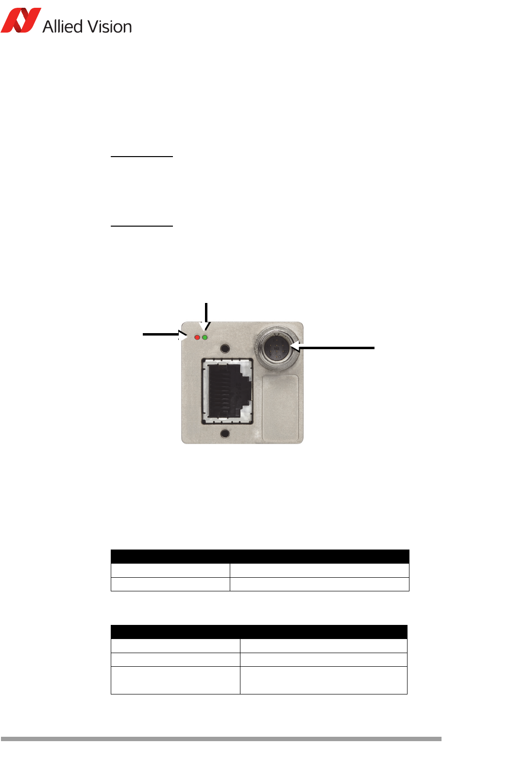
Figure 32: Example: Rear view of Mako camera
LED1 color Status
Solid orange Ethernet link established
Flashing orange Network traffic
Table 22: Status LED (orange)
LED2 color Status
Solid green Camera powered
Slow flashing green Booting routine
Four rapid flashes per second Transmission error.
Contact support@alliedvision.com
Table 23: Status LED (green)
Status LEDs
LED1 (orange)
8-pin
camera
LED2 (green)
I/O connector
(+ ext. power)