
Installation manual


AT-TS24T Connectivity
50
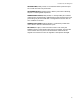
50-Pin Telco Receptacle
The 50-pin Telco receptacles on the AT-TS24T hub are configured as
shown in Figure 48.
For a pin-out table and information on attachment accessories, see
Appendix B.
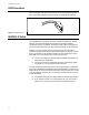
Port Indicators
The port indicators on the AT-TurboStack hub front panels provide visual
diagnostic and activity information for network analysis. The AT-TS24T
has one dual-color LED corresponding to each numbered port connection,
as shown in Figure 49. A central diagnostic key provides a ready reference
to the indicator meanings:
Figure 48: 50-Pin Telco
Receptacle
RD - TD -
RD + TD +
27
26
1
12
3
4
56
7 8 9 10111213141516171819202122232425
26 27 28 29 30 31 32 33 34 35 36 37 38 39 40 41 42 43 44 45 46 47 48 49 50
2
Figure 49: AT-TS24T Port
LEDs
Port activity LEDs
(Network ports 1-12)