x900 Series Switch and SwitchBlade® x908 Expansion Module Installation Guide XEM-1XP XEM-2XP XEM-2XS XEM-12S XEM-12Sv2 XEM-12T XEM-12Tv2 XEM-2XT XEM-24T XEM-STK
XEM_IG.fm Page 2 Wednesday, May 30, 2012 9:24 AM Expansion Modules x900 Series Switch and SwitchBlade® x908 Expansion Module Installation Guide Document Number 613-000032 REV N © 2005-2012 Allied Telesis, Inc. All rights reserved. No part of this publication may be reproduced without prior written permission from Allied Telesis, Inc. Allied Telesis, Inc. reserves the right to change specifications and other information in this document without prior written notice.
XEM_IG.fm Page 3 Wednesday, May 30, 2012 9:24 AM Installation Guide Contents About this Guide .............................................................................................................. 4 Compatible Switches and Operating Systems ........................................................... 5 Compatible Pluggable Optical Modules ....................................................................... 6 Package Contents .......................................................................
XEM_IG.fm Page 4 Wednesday, May 30, 2012 9:24 AM Expansion Modules About this Guide Optional expansion modules (XEMs) enable economical combinations of port type, speed and density in a single switch. Front bays in the switch allow quick and easy installation.
XEM_IG.
XEM_IG.fm Page 6 Wednesday, May 30, 2012 9:24 AM Expansion Modules Compatible Pluggable Optical Modules For the latest list of approved SFP, SFP+ and XFP fibre transceivers plus SFP+ Direct Attach copper modules, contact your authorised Allied Telesis distributor or reseller. See the most current revision available of the XEM datasheet (document number 617-000034) for further information about which SFP, SFP+, and XFP fibre transceivers and SFP+ Direct Attach copper modules are approved for use.
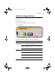
XEM_IG.fm Page 7 Wednesday, May 30, 2012 9:24 AM Installation Guide XEM-1XP 10 Gigabit XFP Port The XEM-1 XP single-port 10 Gigabit Ethernet expansion module features: ■ one XFP port ■ LEDs showing port status ■ support for hot-swappable XFP transceiver modules XEM-1XP Front view XEM-1 XP L/A XFP L/A LINK ACT XFP ENABLED DISABLED FAULT The following LEDs report operations and faults on the XEM-1 XP.
XEM_IG.fm Page 8 Wednesday, May 30, 2012 9:24 AM Expansion Modules For the latest list of approved XFP transceiver modules, contact your authorised Allied Telesis distributor or reseller. See the most current revision available of the XEM datasheet (document number 617-000034) for further information about which XFP transceiver modules are approved for use with the XEM-1XP. Caution Allied Telesis recommends waiting 30 seconds after hot swapping any XEM before resuming normal operations.
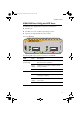
XEM_IG.fm Page 9 Wednesday, May 30, 2012 9:24 AM Installation Guide XEM-2XP Dual 10 Gigabit XFP Ports The XEM-2 XP Dual 10 Gigabit Ethernet expansion module features: ■ two XFP ports ■ four LEDs (one set for each XFP port) showing port status ■ support for hot-swappable XFP transceiver modules Front view XEM-2 XP L/A L/A XFP XFP L/A LINK ACT XFP ENABLED DISABLED XEM-2XP 2 1 FAULT The following LEDs report operations and faults on the XEM-2XP.
XEM_IG.fm Page 10 Wednesday, May 30, 2012 9:24 AM Expansion Modules For the latest list of approved XFP transceiver modules, contact your authorised Allied Telesis distributor or reseller. See the most current revision available of the XEM datasheet (document number 617-000034) for further information about which XFP transceiver modules are approved for use with the XEM-2XP. Caution Allied Telesis recommends waiting 30 seconds after hot swapping any XEM before resuming normal operations.
XEM_IG.fm Page 11 Wednesday, May 30, 2012 9:24 AM Installation Guide XEM-2XS Dual 10 Gigabit SFP+ Ports The XEM-2 XS Dual 10 Gigabit Ethernet expansion module features: ■ two SFP+ ports ■ four LEDs (one set for each SFP+ port) showing port status ■ support for hot-swappable SFP+ fibre transceivers and Direct Attach copper modules 1 2 L/A L/A SFP+ XEM-2XS Front view XEM-2 XS SFP+ L/A LINK ACT SFP+ ENABLED DISABLED FAULT The following LEDs report operations and faults on the XEM-2XS.
XEM_IG.fm Page 12 Wednesday, May 30, 2012 9:24 AM Expansion Modules LED State Description SFP+ Green An SFP+ fibre transceiver or a Direct Attach copper module is installed and enabled. Amber The port is disabled because either a non SFP+ fibre transceiver or a disabled Direct Attach copper module is installed. Amber The SFP+ fibre transceiver is not ready or has a fault. flashing Direct Attach copper modules cannot indicate a fault.
XEM_IG.fm Page 13 Wednesday, May 30, 2012 9:24 AM Installation Guide XEM-12S 100/1000 BASE-X SFP Ports The XEM-12 S 12-port 100/1000BASE-X expansion module features: ■ two rows of 6 SFP ports ■ LEDs showing port status ■ support for hot-swappable SFP transceiver modules ■ NEBS compliant XEM-12S Front view XEM-12 S The following LEDs report operations and faults on the XEM-12 S. LED State Description SFP Green An SFP transceiver module is installed and a link has been established.
XEM_IG.fm Page 14 Wednesday, May 30, 2012 9:24 AM Expansion Modules For the latest list of approved SFP transceiver modules, contact your authorised Allied Telesis distributor or reseller. See the most current revision available of the XEM datasheet (document number 617-000034) for further information about which SFP transceiver modules are approved for use with the XEM-12S. Caution Allied Telesis recommends waiting 30 seconds after hot swapping any XEM before resuming normal operations.
XEM_IG.fm Page 15 Wednesday, May 30, 2012 9:24 AM Installation Guide XEM-12Sv2 100/1000 BASE-X SFP Ports The XEM-12 S 12-port 100/1000BASE-X expansion module features: ■ two rows of 6 SFP ports ■ LEDs showing port status ■ support for hot-swappable SFP transceiver modules XEM-12Sv2 Front view XEM-12 Sv2 The following LEDs report operations and faults on the XEM-12 Sv2. LED State Description SFP Green An SFP transceiver module is installed and a link has been established.
XEM_IG.fm Page 16 Wednesday, May 30, 2012 9:24 AM Expansion Modules For the latest list of approved SFP transceiver modules, contact your authorised Allied Telesis distributor or reseller. See the most current revision available of the XEM datasheet (document number 617-000034) for further information about which SFP transceiver modules are approved for use with the XEM-12Sv2. Caution Allied Telesis recommends waiting 30 seconds after hot swapping any XEM before resuming normal operations.
XEM_IG.
XEM_IG.fm Page 18 Wednesday, May 30, 2012 9:24 AM Expansion Modules Caution Allied Telesis recommends waiting 30 seconds after hot swapping any XEM before resuming normal operations. The switch must fully complete the bootup process before you can hot swap any XEM. Also ensure the XEM fastening thumbscrews are fully tightened. If you are unsure about correct procedures, contact your authorised Allied Telesis distributor or reseller.
XEM_IG.
XEM_IG.fm Page 20 Wednesday, May 30, 2012 9:24 AM Expansion Modules LED State Description D/C (Duplex/ Collision) Green The port is operating in full duplex mode. Amber The port is operating in half duplex mode. Amber flashing Collisions are occurring. Off A link has not been established. Caution Allied Telesis recommends waiting 30 seconds after hot swapping any XEM before resuming normal operations. The switch must fully complete the bootup process before you can hot swap any XEM.
XEM_IG.fm Page 21 Wednesday, May 30, 2012 9:24 AM Installation Guide XEM-2XT Dual 10G BASE-T RJ-45 Ports The XEM-2 XT Dual 10 GBASE-T RJ-45 expansion module features: ■ two 10GBASE-T RJ-45 ports ■ LEDs showing port status Front view XEM-2 XT 1 L/A 2 XEM-2XT L/A L/A 10G LINK ACT The following LEDs report operations and faults on the XEM-2XT. LED State Description L/A (Link Activity) Green A 10 Gbps link has been established. Green flashing 10 Gbps activity is occurring.
XEM_IG.
XEM_IG.fm Page 23 Wednesday, May 30, 2012 9:24 AM Installation Guide LED State Description D/C (Duplex/ Collision) Green The port is operating in full duplex mode. Amber The port is operating in half duplex mode. Amber flashing Collisions are occurring. Off A link has not been established. Caution Allied Telesis recommends waiting 30 seconds after hot swapping any XEM before resuming normal operations. The switch must fully complete the bootup process before you can hot swap any XEM.
XEM_IG.
XEM_IG.fm Page 25 Wednesday, May 30, 2012 9:24 AM Installation Guide A choice of 0.5 m or 2.0 m stacking cables can be ordered separately. For the latest list of approved cables, contact your authorised Allied Telesis distributor or reseller. The Select button resets the stack ID of this switch to 1, and causes the other members of the stack to be renumbered. Use this to put the stack into a predefined configuration for ease of installation.
XEM_IG.fm Page 26 Wednesday, May 30, 2012 9:24 AM Expansion Modules Installation Procedure The installation procedure and XEMs supported by each switch depend on the operating system running on the switch. AlliedWare Plus™ Operating System Switches running the AlliedWare Plus™ operating system support all XEMs.
XEM_IG.fm Page 27 Wednesday, May 30, 2012 9:24 AM Installation Guide ■ Gather necessary tools. You may need a Phillips #2 screwdriver to adjust the thumbscrews on the XEM.
XEM_IG.fm Page 28 Wednesday, May 30, 2012 9:24 AM Expansion Modules 10. Restart the switch and verify the installation. If you have a terminal connected to the asyn0 port, any error message is displayed during startup self-tests. Confirm there is no error message about installation in the log file and that the switch has recognised the XEM.
XEM_IG.fm Page 29 Wednesday, May 30, 2012 9:24 AM Installation Guide 6. Verify the installation. If you have a terminal connected to the asyn0 port, any error message is displayed during installation.
XEM_IG.
XEM_IG.fm Page 31 Wednesday, May 30, 2012 9:24 AM Installation Guide Contacting us With locations covering all of the established markets in North America, Latin America, Europe, Asia, and the Pacific, Allied Telesis provides localized sales and technical support worldwide. To find the representative nearest you, visit us on the Web at www.alliedtelesis.com.