Uplink Module Installation and Safety Guide AT-A35/SX AT-A35/LX AT-A39/T AT-A40/SC AT-A40/MT AT-A41/SC AT-A41/MT AT-A42/GBIC
Uplink Module Uplink Module Installation and Safety Guide Document Number 613-000689 Rev A. Copyright © 2006 Allied Telesis Inc. All rights reserved. No part of this publication may be reproduced without prior written permission from Allied Telesis, Inc. Allied Telesis, Inc. reserves the right to make changes in specifications and other information contained in this document without prior written notice. The information provided herein is subject to change without notice.
Installation and Safety Guide 3 Package Contents The following items are included with each uplink module. Contact your authorised Allied Telesis distributor or reseller if any items are damaged or missing. ■ One uplink module. ■ One Uplink Module Installation and Safety Guide. ■ One warranty card. Compatible Switches Caution Attempting to install an expansion module into a switch which is not compatible may damage the switch and the expansion module.
Uplink Module 2. Gather the tools and equipment you will need. A medium-sized flat-bladed screwdriver may be useful when loosening the uplink module thumbscrews. You should also have any cables required for connecting the uplink module to other network devices. AT-A42/GBIC uplink modules require a GBIC before they can be connected to a network. 3. Remove power to the switch or router. Warning Do not install an uplink module into a switch without first removing power from the switch.
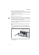
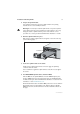
Installation and Safety Guide 5 5. Prepare the uplink module. In an antistatic environment, remove the uplink module from its packing material. Be sure to observe ESD precautions. Warning Do not attempt to install an uplink module or any other expansion option without observing correct antistatic procedures. Failure to do so may damage the switch or uplink module. If you are unsure what the correct procedures are, contact your authorised Allied Telesis distributor or reseller. 6.
Uplink Module 9. Apply power to the switch. The switch’s Fault LED may flash for approximately 10 seconds as it runs internal tests. 10. Check that the Power LED on the switch’s front panel lights green. If the LED fails to light, refer to the Troubleshooting section of the Uplink Module Hardware Reference. 11. Connect the data cables. If fitted, remove the uplink module’s port dust cover, and connect the data cable. Make sure each cable connection is secure. 12. Check the uplink module’s LEDs.
Installation and Safety Guide 7 LEDs for the AT-A42/GBIC: LED State Function L/A Link/Activity Green A 1000 Mbps link is established. Flashing green 1000 Mbps activity is occuring. Flashing amber (and GBIC LED is off) A transmission fault has occured. Off No link is present. Green The switch has recognised the GBIC, the GBIC is a valid model. Green (and L/A LED is flashing green) The port is operating at full-duplex.
Uplink Module LEDs for the AT-A39/T: LED State Function Full Dup/ Half Dup/ Col Green The port is operating at full-duplex. Amber The port is operating at half-duplex. Flashing amber Collisions are occuring. Off No link is present. Green A 1000 Mbps link is established. Activity Flashing green 1000 Mbps activity is occuring. a Amber A 10/100 Mbps link is established. Flashing amber 10/100 Mbps activity is occurring. Off No link is present. a.