Uplink Module Quick Install Guide AT-A35/SX AT-A35/LX AT-A39/T/ AT-A40/SC AT-A40/MT AT-A41/SC AT-A41/MT AT-A42/GBIC
Uplink Module Quick Install Guide Document Number C613-04022-01 REV H. Copyright © 1999-2006 Allied Telesis International, Corp. 19800 North Creek Parkway, Suite 200, Bothell, WA 98011, USA. All rights reserved. No part of this publication may be reproduced without prior written permission from Allied Telesis. Allied Telesis International, Corp. reserves the right to make changes in specifications and other information contained in this document without prior written notice.
Quick Install Guide 3 Models Covered By This Guide ‘This Quick Install Guide includes information on the following models: ■ AT-A35/SX ■ AT-A35/LX ■ AT-A39/T ■ AT-A40/SC ■ AT-A40/MT ■ AT-A41/SC ■ AT-A41/MT ■ AT-A42/GBIC Quick Install Guide updates can be found at www.alliedtelesyn.com/support/ . Compatible Switch Units This section lists all uplink module models, and indicates which switches each model can be installed in.
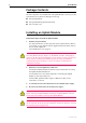
Uplink Module Package Contents The following items are included with each Uplink Module. Contact your sales representative if any items are damaged or missing. ■ One Uplink Module. ■ One Uplink Module Quick Install Guide. ■ One warranty card. Installing an Uplink Module Follow these steps to install an uplink module: 1. Read the safety information For safety information, see the Safety and Statutory Information booklet for your switch.
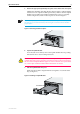
Quick Install Guide 5 5. Remove the appropriate uplink bay face-plate on the switch unit’s front panel AR800 Series Modular Switching Routers, Rapier, Rapier i and AT-8700XL Switches have two uplink module expansion bays. If this is the first Uplink Module to be installed, it should be installed in the top bay (to simplify VLAN configuration). Remove the face-plate as shown in Figure 1. Keep the face-plate for future use.
Uplink Module 8. Secure the Uplink Module to the switch unit Firmly press the Uplink Module until its connectors engage the uplink bay connectors inside the switch unit. Use a screwdriver to tighten the Uplink Module’s screws. Do not over-tighten the screws. 9. For AT-A42/GBIC uplink modules, install the GBIC Slide the GBIC into the uplink’s GBIC slot. Press the GBIC firmly into place. A range of GBICs have been tested and approved for use with AT-A42 uplink modules.
Quick Install Guide 7 Table 1: AT-A35/SX and AT-A35/LX LEDs. LED State Function Activity Flashing Amber Frames are being transmitted or received through the port Off No activity is occurring Table 2: AT-A39/T LEDs.
Uplink Module Table: 4 AT-A42/GBIC LEDs .
Quick Install Guide 9 Information on other expansion options for the AR800, Rapier, Rapier i and AT-8700XL Series: ■ The Network Service Module Quick Install Guide, which outlines the procedure for installing an NSM; and the Network Service Module Hardware Reference, which provides detailed information on NSMs. ■ The Port Interface Card Quick Install Guide, which outlines the procedure for installing PICs; and the Port Interface Card Hardware Reference, which provides detailed information on PICs.