Manual
Manuals
Brands
Allied Telesis Manuals
Computer Hardware
SwitchBlade x8112
211
212
213
214
215
216
217
218
219
220
Chapter 10: Re
placing Modules
212
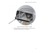
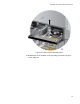
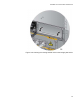
Figure 141. Removing the Positive
Lead Wire from the Te
rminal Block
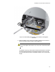
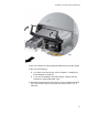
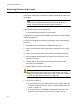
7.
Reinstall the two screws on the
negative (-) and positive (+) terminals.
Refer to Figure 142 on page 213.
1
...
...
210
211
212
213
214
...
...
240