SwitchBlade 4000 Series Switch Hardware Reference AT-SB4108-00 AT-SB4108-60 AT-SB4108-80 AT-SB4104-00 AT-SB4104-80
SwitchBlade Hardware Reference Document Number C613-03060-00 REV H. © 2002-2009 Allied Telesis, Inc. All rights reserved. No part of this publication may be reproduced without prior written permission from Allied Telesis, Inc. Allied Telesis, Inc. reserves the right to change specifications and other information in this document without prior written notice. The information provided herein is subject to change without notice. In no event shall Allied Telesis, Inc.
Hardware Reference 3 Contents Models Covered by this Reference .................................................................... 5 Why You Should Read this Reference ................................................................ 6 Where to Find More Information ....................................................................... 6 SwitchBlade Overview ....................................................................................... 7 Key Hardware Components ..................................
SwitchBlade 4000 Series Switch Port, Connector, and Cable Combinations ...................................................... Using Windows Terminal and Hyperterminal ................................................... Restricted Procedures ...................................................................................... Diagnostics ............................................................................................... Contacting Us ..........................................................
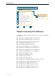
Hardware Reference 5 Documentation Roadmap SwitchBlade Safety and Statutory Information Booklet Hardware Reference Software Reference General Customer Support Chassis & Fan Tray Quick Install Guide Visit www.alliedtelesyn.co.nz for the latest documentation, FAQs, and support information.
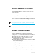
SwitchBlade 4000 Series Switch The latest SwitchBlade Hardware Reference can be found at www.alliedtelesis.com/support/software. Why You Should Read this Reference This reference provides hardware related information for the SwitchBlade, including information on the chassis, switch controllers, line cards, power supplies, and fan tray. The reference has two primary aims: 1. To familiarise you with the SwitchBlade’s hardware features. 2.
Hardware Reference 7 ■ Adobe Acrobat Reader - Provides a facility for viewing online documentation in PDF format. The documents listed here can also be downloaded from the SwitchBlade www.alliedtelesis.com/support/software. SwitchBlade Overview This section provides an introduction to the SwitchBlade’s hardware and operational characteristics. Key Hardware Components SwitchBlade switches are based on a modular design.
SwitchBlade 4000 Series Switch The four slot chassis (AT-SB4104) provides space for the following units: • two switch controller cards (or one switch controller and one bandwidth expander) • four line cards • two PSUs • one AT-SB4151 fan tray Both chassis types are available in either AC or DC power supply. The eight slot AC chassis models can be supplied with either dual or triple power feeds.
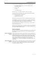
Hardware Reference 9 Power Feed 1 Power Feed 2 Relay DC GOOD DC GOOD DC GOOD FAN GOOD FAN GOOD FAN GOOD POWER PRESENT POWER PRESENT POWER PRESENT AT-SB4162 AC POWER SUPPLY AT-SB4162 AC POWER SUPPLY AT-SB4162 AC POWER SUPPLY PSU 1 PSU 2 PSU 3 Dual Power Feed Connections In the default mode, power feed1 supplies power to PSU 1 and PSU 2, and power feed 2 supplies power only to PSU 3.
SwitchBlade 4000 Series Switch Switching Performance and Characteristics The SwitchBlade architecture is based on a non-blocking wire-speed Layer 2 and 3 switching fabric. Layer 3 switching is performed by line cards as well as switch controllers. As with other Allied Telesis Layer 3 switches, the SwitchBlade includes full multiprotocol routing capabilities. Layer 3 switching performance is determined by the number of switch controllers and line cards that are installed.
Hardware Reference 11 • Line cards. Equivalent cards can be exchanged without having to reconfigure the switch. For example, if an AT-SB-4311 line card is removed and replaced with a new AT-SB-4311 (in the same bay), the new card will use the original card’s configuration (as long as the switch is not restarted before the new card is installed). The next section describes the configuration effects of hot-swapping a line card.
SwitchBlade 4000 Series Switch ■ Whether a power cycle occurred between the create config command and the line card being replaced, and ■ If a power cycle did occur, whether another create config command has been entered. The process flow is shown in Figure 1-1 on page 12. Figure 1-1: The process flow involved in hot swapping a line card out, changing the switch’s configuration, and then hot swapping the line card back in Line card is hotswapped out The switch is reconfigured.
Hardware Reference 13 The most desirable situation is to avoid a power cycle before replacing the line card. However, if a power cycle does occur, the line card’s original configuration is saved by the switch and can be displayed by using the command: show config dynamic Look for “Swapped out” headings in the Switch (post-VLAN and pre-VLAN), STP, VLAN, QOS, and GARP sections.
SwitchBlade 4000 Series Switch The switch’s configuration maintains the swapped-out settings. These result in error messages on start-up, but do not affect the functioning of the switch. The configuration can be manually edited to remove the swapped sections that no longer apply. 4. Line Card 1 has been configured and then removed before the configuration was saved using the create config command.
Hardware Reference 15 # add vlan="v2" port=2.1-2.4 # # vlan swapped out configuration add vlan="v2" port=1.1-1.8 After the new line card is inserted and the create config command is entered, the show config dynamic command displays the following configuration: # # vlan configuration # add vlan="v2" port=2.1-2.4 7. (continuing from the end of Example 4) The wrong line card is accidentally inserted into slot 1. The user realises the mistake and removes the line card.
SwitchBlade 4000 Series Switch Regulatory Standards • EMC: EN55022 class A, FCC class A, and VCCI class I • Immunity testing to EN55024: EN61000-4 levels 2 (ESD), 3 (susceptibility), 4 (fast transients), 5 (power surge), 6 (RF immunity), and 11 (Voltage dips and sags; EN61000-3 levels 2 (Harmonics), and 3 (Flicker) • Safety: UL60950, CAN/CSA-C22.2 No.
Hardware Reference 17 Expansion Bays • Two switch controller bays • Eight line card bays • Three power supply bays • One fan tray bay (compatible with the AT-SB4152 fan tray) Alarm Relays • Two relays (Major and Minor) each located on the rear panel • Normally open and normally closed contacts • Software configurable for a range of environmental and operational events • Suitable for use with DC alarm circuits (12 V DC 1.0 A or 48 V DC 0.
SwitchBlade 4000 Series Switch Environmental Conditions • Operating temperature range: (0 to 40) ºC, (32 to 104) ºF • Storage temperature range: (-25 to +70) ºC, (-13 to +158) ºF • Relative humidity range: 5 to 95% non-condensing Regulatory Standards • EMC: EN55022 class A, FCC class A, and VCCI class I • Immunity testing to EN55024: EN61000-4 levels 2 (ESD), 3 (susceptibility), 4 (fast transients), 5 (power surge), 6 (RF immunity), and 11 (Voltage dips and sags; EN61000-3 levels 2 (Harmonics)
Hardware Reference 19 Mounting System • 19 inch rack mounting • Front rack-mounting brackets incorporated in chassis.
SwitchBlade 4000 Series Switch Cooling • Built-in fan • Monitoring of PSU fans for stalled or slow speed LEDs • Three LEDs indicate power supply status (input, output, and fan status) • For a complete list of LEDs and their functions, see “LEDs and What They Mean” on page 47 Electrical Specifications Per Chassis Type Eight Slot Triple Feed AC Chassis (SB4108-00) • (100 to 240) V AC (50 to 60) Hz input For a fully loaded chassis with eight line cards and a fan tray installed • Maximum continu
Hardware Reference 21 Four Slot Dual Feed DC Chassis (SB4104-80) Fully loaded chassis with four line cards and a fan tray installed • Maximum continuous current draw for each active power feed, 15A within the rated input voltage range. • Maximum inrush current for each PSU (cold start), A within the rated input voltage range. • Accepts positive or negative earthing (grounding) AT-SB4152 Fan Tray (For SwitchBlade 8) Weight • 3.
SwitchBlade 4000 Series Switch AT-SB4211 and AT-SB4211 V2, Switch Controller Weight AT-SB4211 V2 • 2.5 kg SWITCH CONTROLLER LEDs • Three system status and fault LEDs, and two LEDs to indicate status of the ETH0 management port (link activity, full/half-duplex, and collisions) For a complete list of LEDs and their functions, see “LEDs and What They Mean” on page 47.
Hardware Reference 23 AT-SB4215 Bandwidth Expander The bandwidth expander card achieves the performance of the dual controller configuration, without incurring the cost of a second controller card. AT-SB4215 The bandwidth expander card is used in controller slot B to utilise unused internal ports, i.e. those ports that would normally be assigned to line cards 5 to 8 on the 8 slot chassis. This achieves the same level of performance as using two controller cards.
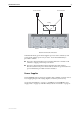
SwitchBlade 4000 Series Switch AT-SB4311 and AT-SB4311 V2 48-Port (RJ-45) Fast Ethernet Line Card Weight AT-SB4311 V2 AUTO MDI / MDI-X 2 1 4 3 6 5 8 7 10 9 12 11 14 13 16 15 18 17 20 19 22 21 24 23 26 25 28 27 30 29 32 31 • 2.
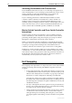
Hardware Reference 25 AT-SB4352 and AT-SB4352 V2 32-Port (MT-RJ) Fast Ethernet Line Card Weight AT-SB4352 V2 100 BASE-FX / MT-RJ D/C L /A D/C L /A D/C L /A 17 D/C L /A D/C L /A D/C L /A D/C L /A D/C L /A • 2.
SwitchBlade 4000 Series Switch AT-SB4412 and AT-SB4412 V2 24-Port Gigabit (RJ-45) Ethernet Line Card AT-SB4412 V2 Weight • L /A 2.
Hardware Reference 27 • 64 MByte RAMBUS packet buffer, enabling traffic bursting to be absorbed. • Either 33 MHz or 40 MHz, depending on the speed of the master card’s PCI bus. Note: The suffix V2 indicates the card's silicon revision level. Certain enhanced features, such as LACP, will only run on cards with a V2 revision level. You can also display the silicon revision of a line card by executing the show switch instance command (V2 revision level cards are displayed as K1).
SwitchBlade 4000 Series Switch AT-SB4442 V2 24-Port Gigabit (SFP) Ethernet Line Card Weight AT-SB4442 V2 • 2.4 kg Ports • Twenty four full duplex SFP ports. SFP ports can be 1000BASE-T copper, or 1000BASE (SX, LX, ZX) fibre, depending on the SFP used. • Auto MDI/MDI-X as default (MDI-X if auto-negotiation is disabled). Where this card is used to replace an 8 port card, a general rule is to first use the centre 8 ports shown within the dotted line.
Hardware Reference 29 Note: The suffix V2 indicates the card's silicon revision level. Certain enhanced features, such as LACP, will only run on cards with a V2 revision level. You can also display the silicon revision of a line card by executing the show switch instance command (V2 revision level cards are displayed as K1). Refer to the Switching Chapter of your SwitchBlade Software Reference for more information on using this command.
SwitchBlade 4000 Series Switch AT-SB4441 and AT-SB4441 V2, 8-GBIC Line Card Weight AT-SB4441 V2 1000BASE-X GBIC • 2.
Hardware Reference 31 AT-SB4541 V2, 1-port 10GBASE-R Gigabit Ethernet Line Card Weight AT-SB4541 V2 • 10GBASE-R 2.
SwitchBlade 4000 Series Switch Alarm Relays and Monitoring This section provides an introduction to the SwitchBlade’s alarm and monitoring capabilities. All SwitchBlade chassis have two alarm relays on their rear panel, and extensive software-based logging, SNMP trap, and trigger monitoring capability. Alarm Relays The SwitchBlade’s two alarm relays (“Major” and “Minor”) can be configured to operate when a number of different environmental and operational events occur.
Hardware Reference 33 Table 1: Alarm and monitoring events. Event Description Power Supply Unit status Initiates alarm and or monitoring events when a Power Supply Unit fault is detected. Power Supply Unit fan status Initiates alarm and or monitoring events when a PSU fan fault is detected. Port status Initiates alarm and or monitoring events when a specified port goes down.
SwitchBlade 4000 Series Switch Click on the document title. 4. To navigate around PDF documents. Use the toolbar buttons, keyboard shortcuts, or commands from the Document menu to page through the document. Click on a bookmark, thumbnail or hypertext link to jump to a specific section or topic. Use the Search command to search for keywords or phrases. For more information about using the Adobe Acrobat Reader, select "Reader Guide" from the Help menu. 5.
Hardware Reference 35 3. To load a file from AT-TFTP Server to the Switch. On a terminal connected to the master switch controller’s RS-232 ASYN0, type the command: LOAD METHOD=TFTP FILE=filename SERVER=ipadd DEST=FLASH where filename is the name of the file to download and ipadd is the IP address of the PC running AT-TFTP Server. 4. To save a TFTP Server log. Select "Save As" from the File menu. TFTP requests are logged to the AT-TFTP Server main window.
SwitchBlade 4000 Series Switch Using the supplied terminal cable, or a cable you have made by following the instructions in “Useful Cables” on page 41, connect your terminal or PC to the RS-232 ASYN0 on the master switch controller.
Hardware Reference 37 To display help on a specific topic, enter: help topic Alternatively, type a question mark (?) at the end of a partially completed command to see a list of valid options. Start-up Procedures When the switch starts up following either a power cycle or an operatorinitiated reboot (using the Reset button or RESTART command), a series of start-up messages is sent to the terminal or PC connected to RS-232 ASYN0 (Figure 2 on page 37). Figure 2: Switch start-up messages.
SwitchBlade 4000 Series Switch Table 3: Switch start-up message classes. Message Meaning INFO An action will be taken by the system. PASS A test has been completed successfully. ERROR An error message that a test has failed, but the system will continue to operate. FAIL An error message that a fatal error condition has caused the system to halt in an unrecoverable fashion. The possible messages and their meanings are: INFO: Self tests beginning. The code loader tests are about to begin.
Hardware Reference 39 The start-up tests have finished. INFO: Downloading switch software. The process of downloading the switch software and vector table from ROM is about to begin. ERROR: Code load retried. FAIL: Code load failed. The load of the code from ROM to RAM failed. The load is retried a number of times. Each time a failure occurs, the ERROR message is displayed. If the maximum number of attempts is reached, the FAIL message is displayed. INFO: Initial download succeeded.
SwitchBlade 4000 Series Switch Figure 3: RS-232 Terminal Port Pin Numbers. Pin 5 Pin 9 Pin 1 Pin 6 DB9 Female Pin View Table 4: Internal DTE pin roles . Pin Role 2 TXD 3 RXD 4 CD 5 GND 6 DTR 7 CTS 8 RTS RJ-45 Management Port (ETH0) Caution. Do not plug a phone jack into any RJ-45 port. Doing so could damage the switch. Use only twisted pair cables with RJ-45 connectors.
Hardware Reference 41 With 10BASE-T/100BASE-TX cables, pins 1 and 2 are used for transmitting data, while pins 3 and 6 are used for receiving data. Table 5 on page 41 lists the RJ-45 Pin assignments. Table 5: RJ-45 Pin assignments. Pin Number Assignment1 1 TX+ 2 TX- 3 RX+ 6 RX- 1. The “+” and “-” signs represent the polarity of the wires that make up each wire pair.
SwitchBlade 4000 Series Switch Figure 4: Pin wiring diagram for a standard DB9 male to female terminal cable. DB9 Male (to switch/DCE) Not connected → (TXD) ← (RXD) ← (CD) (GND) → (DTR) ← (CTS) → (RTS) ← (RING) Pin 1 DB9 Female (to PC/terminal/DTE) 1 2 3 4 5 6 7 8 9 1 2 3 4 5 6 7 8 9 Pin 5 Pin 5 (DCD) (RXD) (TXD) (DTR) (GND) (DSR) (RTS) (CTS) (RING) Pin 1 Cable Pin 6 Pin 9 Pin 9 DB9 Male Pin View Notes: (1) (2) Pin 6 DB9 Female Pin View → Output from switch; ← Input to switch.
Hardware Reference 43 More information on pin assignments for the RS-232 Terminal Port can be found in “Management Interfaces” on page 39. Cables for RJ-45 Ethernet LAN Interfaces For all 10BASE-T/100BASE-TX (10/100BASE) and 10BASE-T/100BASE-TX/ 1000BASE-T (10/100/1000BASE) connections, a twisted pair cable with RJ-45 connectors must be used. 10/100BASE connections require at least two pairs to be used, while 10/100/1000 connections require four pairs.
SwitchBlade 4000 Series Switch software test facility, to test 10/100BASE network and management ports. Table 9 on page 44 lists the RJ-45 crossover wiring pin assignments. Table 9: RJ-45 Pin assignments, two pair crossover cable. End 1 End 2 1 (TX+) 3 (TX+) 2 (TX-) 6 (TX-) 3 (RX+) 1 (RX+) 6 (RX-) 2 (RX-) 1000BASE straight-through cable For 1000BASE network connections, all four pairs are used and the cable is wired in a straight-through configuration.
Hardware Reference 45 1000BASE crossover cable For 1000BASE test cables, all four pairs are used and the cable is wired in a crossover configuration. This cable can also be used, in conjunction with the software test facility, to test 10/100BASE network ports. Table 11 on page 45 lists the pin assignments. Table 11: Pin assignments, 10/100/1000BASE-T RJ-45 four pair crossover cable1 .
SwitchBlade 4000 Series Switch Figure 6: Example output from the SHOW TEST INT command on an AT-SB4411 with ports 3.1 and 3.2 linked by a crossover cable. Board ID Bay Board Name Rev Serial number ---------------------------------------------------------------------------Base 164 AT-SB4411 M1-0 50433214 Duration Details Interface State Result Type (minutes) Data( %OK ) Control ---------------------------------------------------------------------------eth0 testing wait 4 minutes trans 0 TP < 1 BAD ( 0.
Hardware Reference 47 Troubleshooting This section provides information on how to detect and resolve problems with the SwitchBlade and its expansion options. Other sources of useful troubleshooting information are: ■ www.alliedtelesis.com/support/software. ■ The SwitchBlade Software Reference. LEDs and What They Mean The following tables outline how SwitchBlade LEDs report faults and operational activities.
SwitchBlade 4000 Series Switch Table 12: LEDs on the AT-SB4211 Switch Controller. (Continued) LED State Function D/C Green The management port is operating at fullduplex Amber The management port is operating at halfduplex Flashing Collisions are occurring on the management port link (Duplex/Collision) 1. Appears on both controller cards.
Hardware Reference 49 Table 15: LEDs on the AT-SB4441 8-port 1000BASE GBIC Line Card. LED State Function L/A Green A link is open Flashing Green Activity is occurring Amber The port is operating at half-duplex.
SwitchBlade 4000 Series Switch Check these first 1. Check the power cord(s) connection(s). 2. Check that the power supply voltage is stable. 3. Check that the correct data cables are being used and that their connections are secure. 4. Make sure that other network devices are working properly. 5. Use the SHOW INSTALL command to check that the latest software version is loaded. See the SwitchBlade Software Reference for more information about obtaining the latest software version. 6.
Hardware Reference 51 1. Check that the power cord connections are secure. 2. Check that all switches and circuit protection devices are in the ON position. 3. Ensure that the supply voltage is within the operational range for your particular chassis type and power supply. Refer to the section, “Physical and Operating Specifications” on page 15 of this manual. Fault LED is on This can indicate: ■ There is a problem with the switch or PSU. ■ The switch or management software is malfunctioning.
SwitchBlade 4000 Series Switch Switch Controller Card CAM The switch controller card (SB4211) contains two CAM processor chips. Each chip contains 8 k entries of content addressable memory (CAM). These entries contain address locations for the forwarding database of L2/3 addresses and other similar entries such as VLAN identities. Located alongside each processor chip are 3 CAM chips that together provide an additional 96 k entries.
Hardware Reference 53 If the switch controller is installed in a chassis, remove it by following the instructions in the SwitchBlade Switch Controller Quick Install Guide. The quick install guide can be found on the CD-ROM shipped with each switch controller and chassis, and can be downloaded from www.alliedtelesis.com/support/software. Lay the switch controller on a flat surface. 2. Prepare the DIMMs. In an antistatic environment, remove the two DIMMs from their packing material.
SwitchBlade 4000 Series Switch Testing DIMM The switch is unlikely to boot unless the DIMM is correctly installed. The switch controller’s fault LED will flash slowly if the DIMM is not detected. The fault LED will flash quickly if the DIMM is not of an acceptable type. If the switch does boot but you suspect the DIMM is malfunctioning, or if you hot swapped in a switch controller with new DIMM, enter the command: SHOW SYSTEM to display the system information shown in Figure 9 on page 55.
Hardware Reference 55 Figure 9: Example output from the SHOW SYSTEM command for a switch controller with DIMM installed. Switch System Status Time 10:17:43 Date 07-Feb-2002.
SwitchBlade 4000 Series Switch Gigabit Interface Converters (GBICs) The AT-SB4441 line card provides ports for eight GBICs. These are small hot-swappable plug-in transceivers. By selecting the appropriate GBIC type, you can match your SwitchBlade ports to their appropriate network interface. RJ-45 copper, SC and LC fibre GBICs are currently available. GBIC 1000BASE-T Auto-Negotiation The 1000BASE-T GBICs operating in the AT-SB4441 line card will provide only 1000 Mbps full-duplex connections.
Hardware Reference 57 Model Media Type Description AT-SPSX 1000BASE-SX 850nm, 2m to 500m with 50/125µm MM fiber, 2m to 275m with 62.5/125µm MM fiber, LC connector AT-SPLX10 1000BASE-LX 1310nm, 2m to 10km with 9µm SM fiber, 2m to 550m with 50µm MM fiber, 2m to 550m with 62.
SwitchBlade 4000 Series Switch Port, Connector, and Cable Combinations This section provides cabling guidelines for each line card model. Table 18: Cable guidelines for line cards. Model Port Type Connector Type Cable Type1 Maximum Cable Length AT-SB4311 Line Card 10BASE-T/100BASE-TX RJ-45 10BASE-T Category 3 or better 100m (328ft) 100BASE-TX Category 5 or better 100m (328ft) 50/125 or 62.
Hardware Reference 59 Using Windows Terminal and Hyperterminal You can use a PC running terminal emulation software as the manager console, instead of a terminal. There are many terminal emulation applications available for PCs, but the most readily available are the Terminal and HyperTerminal applications included in Microsoft Windows 98, 2000, and XP Professional. In standard Windows installations, HyperTerminal is available from the Communications submenu.
SwitchBlade 4000 Series Switch 3. In the “Connect using” field on the Connect To dialog box, select the COM port on the PC used to connect to the switch. and click the OK button. 4. In the COMn Properties dialog box, set port parameters as follows, and click the OK button.
Hardware Reference 61 5. From the main HyperTerminal window, select Properties from the File menu. Click the Settings tab, and set the Properties dialog box as follows. 6. Click ASCII Setup to display the ASCII Setup dialog box, and ensure the following options are not selected: • Echo typed characters locally • Append line feeds to incoming line ends Set other parameters as necessary and click the OK buttons on both dialog boxes to close them.
SwitchBlade 4000 Series Switch 7. Save the current session by selecting Save from the File menu on the main HyperTerminal window. This creates a connection icon with the name you assigned in the HyperTerminal group. To use the configuration, double-click the connection icon. When the HyperTerminal window appears, press the Enter key several times; the switch’s login prompt is then displayed.
Hardware Reference 63 2. Restart the switch. Restart the switch, either by using a pen or pencil to operate the recessed reset button on the switch controller’s front panel, or by using the terminal to log in and enter the command: RESTART REBOOT See “To log In” on page 35 for more information on how to log in. 3. Enable diagnostics mode during start-up. During the switch start-up process, at the prompt: Force EPROM download (Y)? press [Ctrl/D] on the terminal to enter diagnostics mode.
SwitchBlade 4000 Series Switch Contacting Us With locations covering all of the established markets in North America, Latin America, Europe, Asia and the Pacific, Allied Telesis provides localized sales and technical support worldwide. To find our representative nearest you, visit Allied Telesis on the web at: http://www.alliedtelesis.com/support/software.