
User's Manual

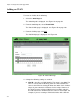


Table Of Contents
- Contents
- Figures
- Preface
- Chapter 1
- AlliedWare Plus™ Version 2.1.2 Web Browser Interface
- Chapter 2
- Starting a Management Session
- Chapter 3
- Basic Switch Parameters
- Setting the System Date and Time
- Setting a Telnet or SSH Server
- Setting a Remote Log Server
- Setting the Switch Information
- Setting the Configuration File
- Managing User Accounts
- Rebooting a Switch
- Upgrading the Software
- Returning the AlliedWare Plus Management Software to the Factory Default Values
- Displaying System Information
- Chapter 4
- Setting Port Parameters
- Chapter 5
- Setting Port Statistics
- Chapter 6
- Setting Port Mirroring
- Chapter 7
- Setting the Port Spanning Tree Protocol
- Chapter 8
- Setting the MAC Address
- Chapter 9
- Setting LACP
- Chapter 10
- Setting Static Port Trunks
- Chapter 11
- Setting Port-based and Tagged VLANs
- Chapter 12
- Setting Switch Spanning Tree Protocols
- Chapter 13
- Setting Internet Group Management Protocol (IGMP) Snooping
- Chapter 14
- Setting MAC Address-based Port Security
- Chapter 15
- Setting RADIUS and TACACS+ Clients
- Chapter 16
- Setting 802.1x Port-based Network Access
- Chapter 17
- Setting IPv4 and IPv6 Management
- Chapter 18
- Setting LLDP and LLDP-MED
- Chapter 19
- Setting sFlow

AlliedWare Plus Version 2.1.2 Management Software Web Browser User’s Guide
133
that spans three switches, assign the Sales VLAN on each switch
the a VID value of 3.
VLAN Name— Specifies a name of a VLAN. A name can be from
1 to 20 characters in length. The first character must be a letter; it
cannot be a number. VLANs are easier to identify if their names
reflect the functions of their subnetworks or workgroups (for
example, Sales or Accounting). A name cannot contain spaces or
special characters, such as asterisks (*) or exclamation points (!).
A name cannot be the same as a name of an existing VLAN on the
switch. If a VLAN is unique in your network, then its name must be
unique as well. A VLAN that spans multiple switches must have the
same name on each switch.
Member Port— Click a port to add it to the VLAN. A “T” indicates a
port is a tagged port. A “U” indicates the port is an untagged port.
Note
For information about tagged and untagged ports, see “Overview”
on page 128.
All Tagged— Click this button to make all ports on the switch
tagged ports.
All Untagged— Click this button to make all ports on the switch
untagged ports.
Deselect All— Click this button to deselect, or unclick, all of the
selected ports.
5. Click Apply to save your changes to the running configuration file.
A confirmation message is displayed.