
Specifications


8-66 Rapier Switch Software Reference
Software Release 2.7.3
C613-03098-00 REV A
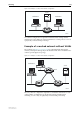
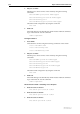
Figure 8-14: Example of meshed network with VLAN tagged ports
Table 8-18 on page 8-67 shows the parameters for creating the VLANs on the
switches and adding ports to the VLANs. Note that by default all VLANs
belong to the default STP, which is disabled at switch start-up.
Note that all three VLANs are created on all three switches, and all uplink
ports belong to all three VLANs. This should be done even though the training
VLAN has no devices on Switch A that need to communicate with Switch B or
C, and Switch C has no devices belonging to the admin VLAN requiring links
to Switch A or B. This is because STP is enabled, and inevitably blocks ports on
one of the three links to prevent a loop in the marketing VLAN. This also
blocks traffic over these ports for the other VLANs. Therefore the training and
admin VLANs must be able to communicate over either of the links on each
switch to ensure full VLAN operation. Failing to include the switches and
uplink ports in the VLANs for which they have no devices attached is likely to
block either the admin or training VLANs access to some of their members.
SWITCH5
Switch A
Server S
Switch B
Switch C
Port 25
Port 24
Port 23
Port 7
Port 6
Port 2Port 1
Port 26 Port 26
Port 26
Port 25
Port 25
Training VLAN
Admin
Training &
Marketing
VLANs
Admin VLAN
Marketing VLAN
Marketing VLAN