
Specifications


Switching 8-53
Software Release 2.7.3
C613-03098-00 REV A
CIST Vectors
Having selected the CIST Root and Designated bridge, the CIST will then deal
with any loops that exist between the regions. It will do this by considering the
following entities, called “vectors” in the following order:
1. CIST External Root Path Cost
2. CIST Regional Root Identifier
3. CIST Internal Root Path Cost
4. CIST Designated Bridge Identifier
5. CIST Designated Port Identifier
6. CIST Receiving Port Identifier
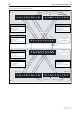
Since there is clearly a loop condition between Switches 3 and 4, the CIST will
inspect each of the vectors. Assuming the two links from the same bridge have
equal path costs, the active link will be selected as the one from the port with
the lowest port number. Hence the path between Port 10 on each switch will be
blocked.
Note the situation if the connections on Switch 4 were reversed, i.e. port 1 of
Switch 3 being connected to port 10 of Switch 4, and port 1 of Switch 4 being
connected to port 10 of Switch 3.
In the above situation, metric 5 above would apply (since metrics 1 through 4
would have the same value). The designated ports would be 1 and 10 on
Switch 3, and since port 1 has the lower (numeric) value, this port would
provide the active link, and the path from its port 10 would be blocked.