
Specifications


8-52 Rapier Switch Software Reference
Software Release 2.7.3
C613-03098-00 REV A
Configuring the CIST Example
Configuring this network involves the same basic steps used in the previous
examples. Note that the only VLAN that is common to both regions is VLAN
12, which uses MSTI 3. These must be explicitly configured to Ports 1 and 10 of
Switches 3 and 4.
For Switch 3
1. Add VLAN 12 to the required ports, as tagged ports.
add vlan=12 po=1,10 frame=tagged
set mstp msti=2 port=10 pathcost=1000
For Switch 4
1. Add VLAN 12 to the required ports, as tagged ports.
add vlan=12 po=1,10 frame=tagged
set mstp msti=2 port=10 pathcost=1000
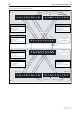
If you configured the network using the steps in the previous example, and
added the shared VLANs to the connecting ports as shown above, the network
now has two regions: Region One representing a company’s Head Office; and
Region Two, representing the company’s Manufacturing Plant. Note that
although each network region is separate, with each of its MSTIs only having
local significance within the region, the data itself still flows between the two
networks and the VLANs in each are still recognised across MSTR boundaries.
The task of preventing loops within the wider network, is the role of CIST. By
inspecting the example network, it is clear that there is a potential loop
between the two regions that CIST must handle.
CIST first allocates root and designated bridges by selecting the bridge with the
lowest identifier as the root. As far as the physical topology is concerned a
good choice for the root bridge would be either of Switches 3 or 4. The network
has been designed to force Switch 3 to become the root by assigning it the
lowest priority identifier in the network (12288), and of course it is also the root
bridge for Region One. Similarly, assigning Switch 4 the priority identifier of
20480 ensures that this bridge becomes the root bridge for Region 2 (because its
priority identifier of 20480 is lower than any other bridge in its region). Switch
4 is also the CIST regional bridge since it offers the lowest path cost from
Region 2 to Switch 3 (the CIST root bridge).
Note that the bridge identifier comprises two parts: a bridge priority part
(more significant), and a bridge MAC address part (less significant). The
multiple spanning tree algorithm uses the bridge identifier when determining
the role of a switch within each spanning tree. The switch with a lower priority
is considered to have better bridge identifier, and is therefore more likely to be
chosen as the root bridge. You can set the CIST bridge priority using the set
mstp cist command.
set mstp cist priority=20480