
Specifications


Switching 8-51
Software Release 2.7.3
C613-03098-00 REV A
other path is blocked. Similarly, the active path between Switches 2 and 3 is
between Port 9 on each switch.
For MSTI 2
Between Switches 1 and 3 there are two paths available, Port 5 to Port 5, and
Port 6 to Port 6. Since no port priority has been explicitly applied, all port
configurations have their defaults. Since all ports have the same speed (100
MBPS) each port has a Port Path Cost of 200,000. Since Port 5 is numerically
lower than Port 6, the active path is the one between Switch 1 Port 5 and Switch
2 Port 5, and the other path is blocked. Similarly, the active path between
Switches 2 and 3, is between Port 9 on each switch.
If you want to make a particular path the active one, use the set mstp msti port
command.
Example:
To balance the load between Switches 2 and 3, set the active path for MSTI 2 to
be between Ports 10 and 10 of each switch. Use the following command to set
the port path cost less than the present default of 200000:
For Switch 2
set mstp msti=2 port=10 pathcost=1000
For Switch 3
set mstp msti=2 port=10 pathcost=1000
Configuration Check
To check the status of the paths and to see which are forwarding and which are
blocked run the show mstp msti port command on page 8-198, for a particular
MSTI and port. From the output, note whether the port is a Root and whether
its status is forwarding or blocking. If the port is a root port and is in the
forwarding state, then its path is Active.
Common and Internal Spanning Tree (CIST)
In addition to the individual MSTIs within each MSTR region, the MSTR
contains a network-wide spanning tree called the Common and Internal
Spanning Tree (CIST). Conceptually, each region represents a virtual bridge.
Internal and external bridge connectivity are two independent functions.
Frames with VIDs allocated to the CIST are subject to the rules and path costs
of the complete bridged LAN as determined by the CIST’s vectors. Frames
other than these are subject to the CIST when travelling outside their region,
and subject to its particular MSTI inside the region.
The following operational rules apply:
■ Each bridge can be a member of only one region.
■ A data frame is associated with a single VID.
■ Data frames with a given VID are associated with either the CIST or their
particular MSTI, but not both.
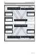
The configuration examples in this section are based on the network shown in
Figure 8-9 on page 8-54. This simple network comprises six LAN bridges and is
basically two networks of the type used in the previous examples, that are
connected back to back.