
Specifications


Switching 8-45
Software Release 2.7.3
C613-03098-00 REV A
Configuring MSTP
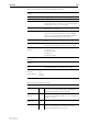
The configuration examples in this section are based on the network shown in
Figure 8-6 on page 8-45. This simple network comprises three LAN bridges
connected in a multi-linked mesh configuration.
The network is configured as a single MSTP region, called a MSTR, and given
the name, Head Office. Two spanning tree instances (MSTIs) are created within
this region called MSTI 2 and MSTI 3. For simplicity only two VLANs are
configured VLAN 12 and VLAN 25; however, a typical MSTI network could
have many more VLANs.
Two MSTIs are created (MSTI 2 and MSTI 3). MSTI 2 is assigned to VLAN12
and MSTI 3 is assigned to VLAN25. The network has several alternative links.
By using MSTP each VLAN can be configured to use its own preferred set of
links
Figure 8-6: Example configuration with MSTP
Switch One
Switch Three
Switch Two
7
8
Drawing Ref Number
10987654321
10987654321
10987654321
VLAN 12 MSTI-2
VLAN 25 MSTI-3
VLAN 25 MSTI-3
VLAN 12 MSTI-2
VLAN 25 M
STI-3
VLAN 25 M
STI-3
VLAN 12 M
STI-2
VLAN 12 M
STI-2
VLAN 12 M
STI-2
VLAN 12 M
STI-2
VLAN 12 MSTI-2
VLAN 12 MSTI-2 VLAN 25 MSTI-3
VLAN 25 MSTI-3