
Install guide

Rapier Layer 3 Gigabit Switch Software Release 2.1.0 5
Rapier Switch Software Release 2.1.0
C613-10200-01 Rev A
Note that this software release does not support hot swapping, so the switch must be
powered down before an NSM is installed or removed. In future software releases, the
Hot Swap button will be used to power down the NSM bay to allow hot swapping.
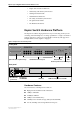
Uplink Modules
Each of the two uplink module expansion bays can support an optional Gigabit
uplink module. The first uplink modules available are:
■
AT-A35SX/SC, 1-port 1000BASE-SX (SC fibre connector)
■
AT-A35LX/SC, 1-port 1000BASE-LX (SC fibre connector)
Network Service Modules (NSMs)
The NSM bay accommodates Network Service Modules (NSMs) designed to
support high speed LAN/WAN technologies. The NSM uses a 32Mhz 32-bit
PCI style bus for high speed data applications. The first NSM to be released is
the AT-AR040 4-PIC NSM, which has 4 PIC bays for installing Port Interface
Cards (PICs). NSMs can be used interchangeably with the AT-AR740 router.
Port Interface Cards (PICs)
The four PIC bays in Network Service Module AT-AR040 accommodate
combinations of the following PIC slide-in interface cards:
■
AR020 PRI E1/T1 PIC, 1 Primary Rate E1/T1 port
■
AR021(S) BRI-S/T PIC, 1 Basic Rate ISDN S/T port
■
AR021(U) BRI-U PIC, 1 Basic Rate ISDN U port
■
AR023 SYN PIC, 1 Synchronous port with universal 50-way AMPLIMITE
connector
■
AR024 ASYN4 PIC, 4 Asynchronous ports with RJ45 connectors.
Most combinations of the PICs in “Port Interface Cards (PICs)” on page 5 can be
installed in the PIC bays in the AT-AR040 NSM. Note the following limitations:
■
Up to two PRI E1/T1 PIC cards (AT-AR020) can be installed in the NSM. If
two PRI E1/T1 PICs are installed, the one must be in the lower row (bay 0
or 1), and the other must be in the upper row (bay 2 or 3).
■
If a AT-AR020 PRI E1/T1 PIC is installed in one of the rows in the NSM
and operating in E1 mode, then this row cannot also have an AT-AR021(S)
BRI-S/T PIC or an AT-AR021(U) BRI-U PICU PIC installed.
The AT-AR040 NSM should be installed the switch, to give it mechanical and
electrostatic protection, before installing PICs in the NSM.
Install a PIC in the lowest numbered NSM PIC bay first, to avoid reallocating interface
numbers when another PIC is installed.
Changing the PICs in the lower numbered NSM bays when PICs of the same
interface type are still installed in the higher numbered PIC bays will change
the interface numbering, and therefore require changes to the software