
Install guide

4 Release Note
Rapier Switch Software Release 2.1.0
C613-10200-01 Rev A
■
1 x RS-232 asynchronous serial port for switch management, with RS-232
DB9 cable for connection to terminal or PC.
■
2 x Uplink bays supporting Gigabit Ethernet uplink modules
■
1 x NSM (Network Service Module) bay
■
A high performance 32-bit PAC slot for PCI accelerator card
■
110-240V AC power supply and optional redundant power supply (RPS)
■
Support for the full AR switching and routing software suite
■
1.5U rack mounting
■
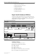
LEDs indicating port activity and system status (Table 1).
Table 1: Rapier 24 front panel LEDs
LED State Function
STATUS
These LEDs indicate the state of the switch.
PWR Green The switch is receiving power and the voltage is in the
acceptable range.
RPS Green A redundant power supply is connected to the switch and
will provide power if the mains power fails or is
disconnected.
Fault Off Normal operation.
Flashing red The switch is booting, running diagnostic tests, writing
messages to FLASH memory, or transferring files using
XMODEM.
Red The switch or management software is malfunctioning.
PORT ACTIVITY
These LEDs indicate the state of the switch ports.
L/A Link/Activity
Green A 100 Mbps link is open.
Flashing green 100 Mps activity is occurring.
Amber A 10 Mbps link is open.
Flashing amber 10 Mps activity is occurring.
D/C Duplex/collision
Green The port is operating at full-duplex.
Amber The port is operating at half-duplex.
Flashing amber Collisions are occurring on the line.
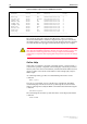
Table 2: Rapier 24 rear panel LEDs
LED State Function
NSM
These LEDs give indications about an NSM installed in the switch.
Swap Green Lit when the NSM is powered down and may be hot swapped. Only
lit if the software also supports hot swapping.
In Use Green Lit when an NSM is installed. If the software supports hot
swapping, it indicates that the NSM is powered up and may not be
swapped.