
Install guide

Rapier Layer 3 Gigabit Switch Software Release 2.1.0 25
Rapier Switch Software Release 2.1.0
C613-10200-01 Rev A
On the Rapier switch, packet storm protection limits cannot be set for each
individual port, but can be set for each processing block of ports. On the Rapier
24 switch the processing blocks are ports 1-8, 9-16, 17-24, and a processing
block each for the uplink ports 25 and 26. The Rapier 24 switch only allows one
limit to be set for all three packet types, while allowing each of the packet types
to be either limited to this value, or unlimited (NONE).
The SHOW SWITCH PORT command displays the packet storm protection
settings (Figure 8 on page 19).
SHOW SWITCH PORT=port-list
Port mirroring
Port mirroring allows traffic being received and transmitted on a switch
Ethernet port to be sent to another port, usually for the purposes of capturing
the data with a protocol analyser. The mirror port to which traffic is sent is set
using the command:
SET SWITCH MIRROR={NONE|port}
The mirror port cannot be part of a trunk group.
Traffic received on a port, traffic transmitted, or both can be mirrored. This is
specified, along with the source port(s) from which traffic is sent to the mirror
port, using the command:
SET SWITCH PORT=port-list MIRROR={NONE|RX|TX|BOTH}
The MIRROR parameter specifies the role of these port(s) as a source of mirror
traffic. If the value NONE is specified, no traffic received or sent on these
port(s) will be mirrored. If the value RX is specified, all traffic received on these
port(s) will be mirrored. If the value TX is specified, all traffic transmitted on
these port(s) will be mirrored. If the value BOTH is specified, all traffic received
and transmitted will be mirrored. Traffic will actually only be mirrored if there
is a mirror port defined and the mirror feature is enabled. The default is
NONE.
By default mirroring is disabled, no mirror port is set, and no source ports are
set to be mirrored. Mirroring is enabled and disabled using the commands:
ENABLE SWITCH MIRROR
DISABLE SWITCH MIRROR
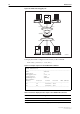
Virtual LANs
A Virtual LAN is a software-defined broadcast domain. The switch’s VLAN
feature allows the network to be segmented by software management,
improving network performance. Workstations, servers, and other network
equipment connected to the switch can be grouped according to similar data
and security requirements. Several VLANs can be connected to the same
switch. Devices that are members of a VLAN only exchange data with each
other through the switching capabilities of the switch. Further flexibility can be
gained by using VLAN tagging. To exchange data between devices in separate
VLANs, the switch’s routing capabilities are used.
By default the switch is configured to include all ports in a single default port-
based VLAN, with no VLAN tagging required on incoming frames, or added
to outgoing frames. If all the devices on the physical LAN are to belong to the
same logical LAN, that is, the same broadcast domain, then the default settings
will be acceptable, and no additional VLAN configuration is required.