
Specifications


32 Rapier Series Switch
C613-03020-00 REV J
NSM LEDs
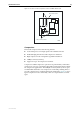
The LEDs in Table 21 are located on the face-plate of AT-AR048 NSMs
NSMs are expansion options and must be purchased separately. They can be
used with all Rapier models except the Rapier 48, Rapier 48i, G6, G6F/SX,
G6F/LX, and G6F/MT.
The AT-AR040 NSM unit has no independent LEDs. See Table 11 on page 28 for
information about related LEDs found on the base-unit switch or router.
The LEDs in Table 20 are located on the face-plates of AT-AR041 and AT-AR042
NSMs.
Table 20: AT-AR041 and AT-AR042 LEDs
LED State Function
Active Green Lit when the BRI has successfully
completed the exchange of INFO 1 and
INFO 2 signals, and INFO 3 and INFO 4
signals are present on the link. This
means the ISDN interface is correctly
connected to a working NT device.
Off No BRI activity is occurring.
Data Amber Pulses when HDLC packets are being
exchanged between the switch or router
and the ISDN switch over the B and D
channels.
Off No data exchange is occurring.
Table 21: AT-AR048 LEDs
LED State Function
Active Green Lit when the Line Interface Unit (LIU) is receiving
a signal
Loop Green Lit when any loopback is active
LOS Amber Lit when the received signal is lost. This usually
indicates a network disruption, such as a cable
being disconnected or a device failure
LOF Amber Lit when the DS3 framer cannot extract valid
frames from the received signal
AIS Amber Lit when an Alarm Indication Signal is detected
FERF Amber Lit when a Far End Receive Failure signal is
detected. This indicates the far end is receiving
an AIS, LOS, or LOF signal