
Specifications


30 Rapier Series Switch
C613-03020-00 REV J
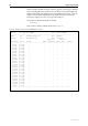
Table 15: Switch Port LEDs (Rapier 16F-FX/SC and 16Fi-FX/SC, and
Rapier 16F-FX/MT-RJ and 16Fi-FX/MT-RJ)
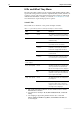
Uplink Module LEDs
The following tables may be helpful when diagnosing possible operational
faults. These LEDs are located on the face-plate of the respective Uplink
Module model. Uplink Modules are expansion options and must be purchased
separately.
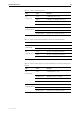
1. Early versions of the AT-A39/T operate at 1000 Mbps only. 10/100/1000
Mbps operation is available only if the AT-A39/T Uplink Module is installed
in a Rapier G6, Rapier G6F or Rapier i model, otherwise operation is fixed
at 1000 Mbps.
LED State Function
L/A
(Link/Activity)
Green A 100 Mbps link is open
Flashing Green 100 Mbps activity is occurring
D/C
(Duplex/Collision)
Green The port is operating at full-duplex
Amber The port is operating at half-duplex
Flashing Amber Collisions are occurring on the line
Table 16: Uplink Module LEDs (AT-A35-SX/SC and AT-A35-LX/SC)
LED State Function
Link Green The port is receiving light
Off No link is present
Activity Flashing Amber Frames are being transmitted or received
through the port
Off No activity is occurring
Table17: Uplink Module LEDs (AT-A39-T/RJ-45)
LED State Function
Full Dup/Half
Dup/Col
Green The port is operating at full-duplex
Amber The port is operating at half-duplex
Flashing amber Collisions are occurring
Off No link is present
Activity Green A 1000 Mbps link is open
Flashing green 1000 Mbps activity is occurring
Amber
1
A 10/100 Mbps link is open
Flashing Amber
1
10/100 Mbps activity is occurring
Off No link is present