Rapier Series Switch Hardware Reference Rapier 24i Rapier 48i Rapier 16fi
Rapier Switch Hardware Reference Document Number C613-03020-00 REV J © 1999-2006 Allied Telesis Inc. All rights reserved. No part of this publication may be reproduced without prior written permission from Allied Telesis Inc. Allied Telesis Inc. reserves the right to change specifications and other information in this document without prior written notice. The information provided herein is subject to change without notice. In no event shall Allied Telesis Inc.
Hardware Reference 3 Contents Models Covered By This Reference .................................................................... 4 Why You Should Read This Document .............................................................. 4 Hardware Overview .......................................................................................... 5 Rapier Switch Models ................................................................................. 7 Rapier G6 ...................................................
Rapier Series Switch Models Covered by this Document This Hardware Reference includes information on the following models: ■ Rapier G6 6-port 100BASE-TX/1000BASE-T (RJ-45 connectors) ■ Rapier G6F-LX/SC 6-port 1000BASE-LX (SC fibre connectors) ■ Rapier G6F-SX/SC 6-port 1000BASE-SX (SC fibre connectors) ■ Rapier G6F-SX/MT-RJ 6-port 1000BASE-SX (MT-RJ fibre connectors) ■ Rapier 8/8MT 8-port 10BASE-T/100BASE-TX (RJ-45 connectors) plus 8-port 100BASE-FX (MT-RJ fibre connectors) ■ Rapier 8/8SC 8-po
Hardware Reference 5 Hardware Overview This section provides an overview of the hardware features for the Rapier Switch series. Hardware descriptions for Uplink Modules, NSMs, and PICs can be found in their respective hardware references. These references can be found on the CD-ROM bundled with your switch, or can be downloaded from from www.alliedtelesis.com/support/software.
Rapier Series Switch Power Supply Unit AC models • Universal 110/240 VAC 50/60 Hz input • Redundant DC Power connection DC models • 48 VDC (39-60 VDC is acceptable) • 4 Amps • Positive or negative earthing (grounding).
Hardware Reference 7 Network Service Module (NSM) Bay (Not included on the Rapier 48, 48i, G6, G6F/SX, or G6F/LX.) • Support for one 32-bit PCI based WAN module • Modules will include hot swap capability with future software versions Rapier Switch Models This section provides hardware descriptions for individual switch models.
Rapier Series Switch Rapier G6F-SX/SC (Figure 3) • 6-port 1000BASE-SX (SC fibre connectors) • Two 10/100/1000BASE uplink bays • Layer 3 Managed Switch Figure 3: Front panel of the Rapier G6F/SX Rapier G6F-SX/MT-RJ (Figure 4) • 6-port 1000BASE-SX (MT-RJ fibre connectors) • Two 10/100/1000BASE uplink bays • Layer 3 Managed Switch Figure 4: Front panel of the Rapier G6F/MT Rapier G6f Layer 3 Gigabit Ethernet Switch 7 RS-232 TERMINAL PORT PORT ACTIVITY 1000BASE-SX / MT-RJ ASYN0 1 L /A 2
Hardware Reference 9 Rapier 8/8SC (Figure 6) • 8-port 10BASE-T/100BASE-TX (RJ-45 connectors) • 8-port 100BASE-FX (SC fibre connectors) • Two 1000BASE uplink bays • One Network Service Module bay (with support for various WAN interface cards) • One PCI Accelerator Card (PAC) Slot • Layer 3 Managed Switch Figure 6: Front panel of the Rapier 8/8SC 1 2 3 L /A 4 L /A 5 L /A 6 L /A 7 L /A Rapier 8/8 8 L /A L /A L /A 17 PORT ACTIVITY L /A D/C D/C D/C D/C D/C D/C D/C D/C 9
Rapier Series Switch Figure 8: Front panel of the Rapier16Fi-FX/MT.
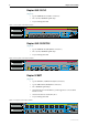
Hardware Reference 11 Rapier 24 (Figure 11) • 24-port 10BASE-T/100BASE-TX (RJ-45 connectors) • Two 1000BASE uplink bays • One Network Service Module bay (with support for various WAN interface cards) • One PCI Accelerator Card (PAC) Slot • Auto-negotiating Layer 3 Managed Switch Figure 11: Front and rear panels of the Rapier 24 (AC model) Front panel Layer 3 Fast Ethernet Switch 25 10BASE-T / 100BASE-TX 1X 3X 5X 7X 9X 11X 13X PORT ACTIVITY 15X 17X 19X 21X 23X L /A 100M LINK / D/
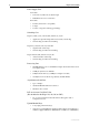
Rapier Series Switch Rapier 24i (Figure 12) • 24-port 10BASE-T/100BASE-TX (RJ-45 connectors) • Two 10/100/1000BASE uplink bays • One Network Service Module bay (with support for various WAN interface cards) • One PCI Accelerator Card (PAC) Slot • Auto-negotiating Layer 3 Managed Switch • Enhanced switching core Figure 12: Front panel of the Rapier 24i.
Hardware Reference 13 Online Documentation This section contains instructions on how to view online documentation on the CD-ROM. Adobe Acrobat Reader must be installed on your computer to view the documentation; you can install it from the CD. 1. Insert the Documentation and Tools CD in the CD-ROM drive. If the browser menu does not appear, select Run from the Start menu. Then type d:\start.exe (where d: is the CD-ROM drive) in the text box, and click the OK button. 2.
Rapier Series Switch AT-TFTP Server This section provides information on how to access and use AT-TFTP Server. AT-TFTP Server can be used to transfer configuration files as well as to download software patches and version releases. To use AT-TFTP Server, follow these steps 1. If AT-TFTP Server has not yet been installed. Install it now from the Rapier Switch Documentation and Tools CD-ROM. Choose AT-TFTP Server from the Start > Programs > Allied Telesis > AT-TFTP Server menu. 2.
Hardware Reference 15 Switch Startup This section outlines the log in and start-up procedures for your switch. Although the switch will perform basic switching operations without being configured, you will need to go through these log in and start-up procedures if you wish to configure the switch and access its full layer 3 switching capabilities. To Log In Using the supplied RS-232 DB9 straight-through cable, connect your terminal or PC to the RS-232 Terminal Port on the switch’s front panel.
Rapier Series Switch To access help files To display a list of help topics, enter: help To display help on a specific topic, enter: help topic Alternatively, type a question mark (?) at the end of a partially completed command to see a list of valid options. Startup Procedures When the switch starts up following either a power cycle or an operatorinitiated reboot (using the Reset button or RESTART command), a series of start-up messages is sent to the RS-232 Terminal Port (Figure 15).
Hardware Reference 17 During the start-up process the switch will generate four different types of messages. All messages are preceded by one of the words INFO, PASS, FAIL, or ERROR. The significance of these words is shown in Table 2. Table 2: Switch start-up message classes Message Meaning INFO An action will be taken by the system. PASS A test has been completed successfully. ERROR An error message that a test has failed, but the system will continue to operate.
Rapier Series Switch INFO: Self tests complete. The start-up tests have finished. INFO: Downloading switch software. The process of downloading the switch software and vector table from ROM is about to begin. ERROR: Code load retried. FAIL: Code load failed. The load of the code from ROM to RAM failed. The load is retried a number of times. Each time a failure occurs, the ERROR message is displayed. If the maximum number of attempts is reached, the FAIL message is displayed.
Hardware Reference 19 Switch Interfaces This section provides pin assignments for the switch’s RS-232 Terminal Port and RJ-45 ports, and the Redundant Power Supply (RPS) connector. If you have installed a Port Interface Card (PIC), pin assignments for these can be found in the Port Interface Card Hardware Reference (which is included on the Documentation and Tools CD-ROM bundled with your switch, or can be downloaded from from www.alliedtelesis.com/support/software).
Rapier Series Switch Switch RJ-45 Ports Caution. Do not plug a phone jack into any RJ-45 port. Doing so could damage the switch. Use only twisted pair cables with RJ-45 connectors. For 10BASE-T/100BASE-TX connections, a twisted pair cable must be used. Each pair is identified by two different colours. For example, one wire might be red, and the other red with a white stripe. An RJ-45 connector must be fitted to both ends of the cable. Figure 17 illustrates the pin layout for RJ-45 connectors.
Hardware Reference 21 If a twisted pair cable is used to join two ports and either both ports are labelled with an “X” or neither port is labelled with an “X”, a crossover must be included in the wiring. Table 6 lists the RJ-45 crossover wiring pin assignments. Table 6: RJ-45 Pin assignments, crossover cable End 1 End 2 1 (TX+) 3 (TX+) 2 (TX-) 6 (TX-) 3 (RX+) 1 (RX+) 6 (RX-) 2 (RX-) For 1000BASE-T RJ-45 cables, all four pairs are used and the cable is wired in a straight-through configuration.
Rapier Series Switch Redundant Power Supply AC models of Rapier Switches have a Redundant Power Supply (RPS) connector on their rear panel. Table 8 lists the connector’s pin numbers and pin functions. Table 8: RPS Connector Pin Numbers and Functions Pin Number Function 1 +12 VDC 2 Remote Sense (RS) +5 VDC 3 Remote Sense (RS) Ground 4 Remote Sense (RS) +3.3 VDC 5 Redundant Power Supply (RPS) Present 6 Ground (+3.
Hardware Reference 23 Switch Cables and Loopback Plugs This section describes how to make cables for connecting the switch’s interfaces to networks, terminals, and printers. How to make loopback plugs for testing switch interfaces is also described. Descriptions of cables and loopback plugs for PIC interfaces can be found in the Port Interface Card Hardware Reference.
Rapier Series Switch Figure 19: Pin wiring diagram for a DCE RS-232 Terminal Port (DB9 female connector) male to male modem cable DB9 Male (to switch/DCE) Not connected → (TXD) ← (RXD) ← (CD) (GND) → (DTR) ← (CTS) → (RTS) (RING) Pin 1 DB9 Male (to modem/DCE) 1 2 3 4 5 6 7 8 9 3 (TXD) 2 (RXD) 1 (DCD) 5 (GND) 4 (DTR) 8 (CTS) 7 (RTS) 9 6 Not connected Pin 5 Pin 5 Pin 1 Cable Pin 6 Pin 9 Pin 9 DB9 Male Pin View Notes: (1) (2) Pin 6 DB9 Male Pin View → Output from switch; ← Input to switch C
Hardware Reference 25 Loopback Plugs for Testing Switch Interfaces Loopback plugs are used in conjunction with the Test Facility software to test the physical interfaces on the switch and some PICs (see the “Test Facility” section beginning on page 22 of this Reference, and the Test Facility chapter of the Rapier Switch Software Reference).
Rapier Series Switch Rapier Switches and their expansion options support a wide range of interface types, including Ethernet, asynchronous, synchronous, Basic Rate ISDN and Primary Rate ISDN. Each interface type (except Ethernet interfaces on the ATAR026) can be tested independently using the Test Facility software. The following examples show how to test specific interfaces. Test results are displayed with the command: SHOW TEST This produces a display similar that shown in Figure 21.
Hardware Reference 27 10/100 Ethernet LAN Port Tests A loopback plug is required to run the first part of the Ethernet LAN test. See “Loopback Plugs for Testing Switch Interfaces” on page 25 for details of how to make a loopback plug. To start an Ethernet interface test, use the command: ENABLE TEST INT=PORTn where n is the Ethernet interface number. The test will run for 4 minutes. Use the show test command to observe the test progress.
Rapier Series Switch LEDs and What They Mean The following tables outline how the Switch, Uplink Module and PIC LEDs report faults and operational activities. Uplink Modules, NSMs, and PICs are expansion options and can be purchased separately. Contact an Authorised Allied Telesis distributer or reseller, or visit from www.alliedtelesis.com for more information on purchasing expansion options. Switch LEDs These LEDs are on the front or rear panels of Rapier Switches.
Hardware Reference 29 Table 12: Switch Port LEDs (Rapier G6) LED State Function L/A Green A 1000 Mbps link is open Amber A 10 Mbps or 100 Mbps link is open Flashing Green 1000 Mbps activity is occurring Flashing Amber 10 Mbps or 100 Mbps activity is occurring Green The port is operating at full-duplex Amber The port is operating at half-duplex Flashing Amber Collisions are occurring on the line (Link/Activity) D/C (Duplex/Collision) Table 13: Switch Port LEDs (Rapier G6F-LX/SC, G6F-SX/
Rapier Series Switch Table 15: Switch Port LEDs (Rapier 16F-FX/SC and 16Fi-FX/SC, and Rapier 16F-FX/MT-RJ and 16Fi-FX/MT-RJ) LED State Function L/A Green A 100 Mbps link is open Flashing Green 100 Mbps activity is occurring Green The port is operating at full-duplex Amber The port is operating at half-duplex Flashing Amber Collisions are occurring on the line (Link/Activity) D/C (Duplex/Collision) Uplink Module LEDs The following tables may be helpful when diagnosing possible operational
Hardware Reference 31 Table: 18 AT-A40/SC, AT-A40/MT, AT-A41/SC and AT-A41/MT LEDs1 LED State Function Activity/Link/Fault Green A link is open and the port is enabled Flashing green 100 Mbps activity is occurring Flashing amber (and lower LED is Off) The link has failed at the remote end Off No link is present Green The port is operating at full-duplex Amber The port is operating at half-duplex Flashing amber Collisions are occurring Off No link is present Alternate flashing of upper
Rapier Series Switch NSM LEDs NSMs are expansion options and must be purchased separately. They can be used with all Rapier models except the Rapier 48, Rapier 48i, G6, G6F/SX, G6F/LX, and G6F/MT. The AT-AR040 NSM unit has no independent LEDs. See Table 11 on page 28 for information about related LEDs found on the base-unit switch or router. The LEDs in Table 20 are located on the face-plates of AT-AR041 and AT-AR042 NSMs.
Hardware Reference 33 PIC LEDs PICs are expansion options and must be purchased separately. They can only be used if an AT-AR040 NSM is installed in the switch. NSMs (and therefore PICs) can be used with all Rapier models except the Rapier 48, Rapier 48i, G6, G6F/SX, G6F/LX, and G6F/MT. These LEDs are located on the face-plate of the respective PIC.
Rapier Series Switch Table 25: PIC LEDs (AT-AR023 SYN) LED Function Tx Lit when data is being transmitted over the synchronous interface. Rx Lit when data is being received over the synchronous interface. Table 26: AT-AR026 4ETH PIC LED functions (Two LEDs per port) LED Function Left Lit when the port is operating at 100Mbps and full duplex. Right Lit when a link has been established. Flashing when data is being transmitted through the port.
Hardware Reference 35 Perform the following steps in sequence: 1. Make sure the data cable connections are secure. 2. Make sure the device at the other end of the connection is switched on and working properly. 3. Check that the data cable is wired correctly. 4. If you can, log in and check the port status. See “To Log In” on page 12 for more information on how to log in. 5.
Rapier Series Switch 5. Download the latest software version. See the Rapier Switch Software Reference for more information on how to obtain the latest software version release. Expansion Options This section provides an overview of the expansion options for Rapier Switches. The following expansion options were available when this Reference was written. See your Authorised Allied Telesis distributer or reseller, or visit from, www.alliedtelesis.com to see if any new options are available.
Hardware Reference 37 • Rapier 16F-FX/MT • Rapier 16Fi-FX/MT • Rapier 8/8SC • Rapier 8/8MT NSMs slot into a base-unit switch and either directly provide additional interfaces, or provide multiple slots where additional interfaces can be added. The following NSMs are available: ■ AT-AR040 (4 Port Interface Card (PIC) slots) ■ AT-AR041 (8 BRI S/T WAN Ports) ■ AT-AR042 (4 BRI S/T WAN Ports) ■ AT-AR048 (1 unchannelised DS3 port)1 1.
Rapier Series Switch other documentation can be found on the CD-ROM bundled with your switch, or at www.alliedtelesis.com/support/software. PCI Accelerator Cards (PACs) PCI Accelerator Cards (PACs) provide additional processing features or performance, but do not add extra physical interfaces to the switch. A PAC can be installed in the dedicated PAC slot on all Rapier switches except the Rapier 48, Rapier 48i, Rapier G6, and Rapier G6F. PACs should only be installed by authorised service personnel.
Hardware Reference 39 Figure 22: Location of main components on the AT-AR061 ECPAC card. PAC Connector Hole for PAC fastner Holes for PAC fasteners PAC Compression PAC-based compression has the following features: ■ Local 32-bit processor for high speed control and data transfer. ■ Dedicated high performance 32-bit compression hardware. ■ High compression ratio Lempel-Ziv algorithm in hardware. ■ 2 MBytes of history memory. ■ Support for up to 127 compression channels.
Rapier Series Switch Figure 23: Typical hardware compression ratios by file type Compression Ratio 7 6 5 4 3 2 1 0 Font Program Window Text Object Spread C source sheet EPS Bitmap TIFF File Type CMPRATIO Encryption PAC-based encryption has the following features: ■ Local 32-bit processor for high speed control and data transfer. ■ Dedicated high performance 32-bit Data Encryption Standard – DES and Triple DES (3DES) – hardware.
Port, Connector, and Cable Combinations Table 28: Cable guidelines Model Port Type(s) Connector Type(s) Cable Type1 Maximum Cable Length Rapier 8/8SC 10BASE-T/ 100BASE-TX RJ-45 10BASE-T Category 3 or better 100m (328ft) 100BASE-TX Category 5 or better 100m (328ft) 50/125 or 62.
Rapier Series Switch Using Windows Terminal and Windows Hyperterminal You can use a PC running terminal emulation software as the manager console, instead of a terminal. There are many terminal emulation applications available for PCs, but the most readily available are the Terminal and HyperTerminal applications included in Microsoft Windows 98, 2000, and XP Professional. In standard Windows installations, HyperTerminal is available from the Communications submenu.
Hardware Reference C613-03020-00 REV J 43 3. In the “Connect using” field on the Connect To dialog box, select the COM port on the PC used to connect to the switch. and click the OK button. 4. In the COMn Properties dialog box, set port parameters as follows, and click the OK button.
Rapier Series Switch 5. From the main HyperTerminal window, select Properties from the File menu. Click the Settings tab, and set the Properties dialog box as follows. 6. Click ASCII Setup to display the ASCII Setup dialog box, and ensure the following options are not selected: • Echo typed characters locally • Append line feeds to incoming line ends Set other parameters as necessary and click the OK buttons on both dialog boxes to close them.
Hardware Reference 45 7. Save the current session by selecting Save from the File menu on the main HyperTerminal window. This creates a connection icon with the name you assigned in the HyperTerminal group. To use the configuration, double-click the connection icon. When the HyperTerminal window appears, press the Enter key several times; the switch’s login prompt is then displayed. Restricted Procedures This section contains procedures that should only be performed by authorised service personnel.
Rapier Series Switch 2. Restart the switch. Restart the switch, either by using a pen or pencil to operate the recessed reset button on the front panel, or by using the terminal to log in and enter the command: RESTART REBOOT See “To Log In” on page 12 for more information on how to log in. 3. Enable diagnostics mode during startup. During the switch start-up process, at the prompt: Force EPROM download (Y)? press [Ctrl/D] on the terminal to enter diagnostics mode.
Hardware Reference 47 Installing a PAC PACs can be installed in all Rapier switches except the Rapier 48, Rapier 48i, Rapier G6, and Rapier G6F. PACs should only be installed by authorised service personnel. Unauthorised opening of the switch’s lid may cause danger of injury from electric shock, damage to the switch, and invalidation of the product warranty. Before you begin 1. Check that you have the correct tools and equipment. You will need a medium-sized posidrive screwdriver. 2.
Rapier Series Switch Figure 25: Location of PAC slot and pillar mounts on a Rapier base board PAC slot Boot EPROMs Fan PAC pillar mounts 8PACslot 6. Insert the PAC. Position the PAC over the PAC slot on the switch base card, making sure that the support pillars located on the switch base card are aligned with the holes provided on the PAC. This ensures that the connector on the PAC is correctly aligned with the slot on the switch base card. Press the connector firmly into place.
Hardware Reference 49 correctly plugged into the slot on the switch’s base board. Repeat the installation process, paying particular attention to Step 6. Use the show system command again, and if the display is still not correct, contact your authorised Allied Telesis distributor or reseller. If you have any difficulty with the PAC at any time, contact your authorised Allied Telesis distributor or reseller and quote the serial numbers of both the base card on the switch and the PAC.
Rapier Series Switch Next, check the PAC’s status using the command: SHOW LOG to display a log of PAC events. A typical display is shown in Figure 27. Figure 27: Example output from the SHOW LOG command for a Rapier switch with an AT-AR061 ECPAC card installed Date/Time S Mod Type SType Message -------------------------------------------------------------------------15 00:05:50 4 ENCO ENCO PAC 7751 Found.
Hardware Reference 51 Figure 28 shows a typical output. The status of the test will be shown in the right-hand column. For further information on the meanings of the other figures, see the “Test Facility” chapter of your switch’s Software Reference.
Rapier Series Switch Replacing Boot EPROMs Rapier Switches have two 512 kByte boot EPROMs. The boot EPROMs contain bootstrap code, which loads the main code from a software release file in FLASH memory. In rare circumstances the boot EPROM(s) may need to be changed. Boot EPROMs should not need to be replaced, except in rare circumstances. Contact your Authorised Allied Telesis distributor or reseller before replacing any boot EPROMs. To change the boot EPROMs 1.
Hardware Reference 53 Figure 29: EPROM locations Boot EPROMs (Rapier 8/8MT, 8/8SC, 16F-FX/MT-RJ, 16Fi-FX/MT-RJ, 16F-FX/SC, 16Fi-FX/SC) PAC slot Boot EPROMs (Rapier G6, G6F-LX/SC, G6F-SX/SC, and G6F-SX/MT-RJ) Fan r24eprom 7. Insert the new boot EPROMs. Insert the new boot EPROMs one at a time, using as a reference the location number printed on the CPU board (e.g., “0” and “1”) and Figure 29 above. Check that the boot EPROMs are firmly seated.
Rapier Series Switch Figure 30: Example output from the SHOW INSTALL command Install Release Patch -----------------------------------------------------------Temporary Preferred flash:load\86s-210.rez Default EPROM (86s-2.1.0) -----------------------------------------------------------Current install -----------------------------------------------------------Preferred flash:load\86s-210.
Hardware Reference 55 ■ The Uplink Module Quick Install Guide, which outlines the procedure for installing an Uplink Module; and the Uplink Module Hardware Reference, which provides detailed information on Uplink Modules. ■ AT-TFTP Server for Windows, for downloading software releases. ■ Adobe Acrobat Reader, for viewing online documentation. You can also download these documents and updates from www.alliedtelesis.com/support/software.