
Specifications


18 Rapier Series Switch
C613-03020-00 REV N
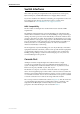
Figure 19: RS-232 Terminal Port Pin Numbers
See “Terminal and Modem Cables” on page 28 for more information on
connection options for the RS-232 console ports.
RJ-45 Ports
For 10BASE-T/100BASE-TX connections, a twisted pair cable must be used.
Each pair is identified by two different colours. For example, one wire might be
red, and the other red with a white stripe. An RJ-45 connector must be fitted to
both ends of the cable. Figure 20 illustrates the pin layout for RJ-45 connectors.
Caution Do not plug a phone jack into an RJ-45 switch port because you could
damage the switch. Use only twisted pair cables with RJ-45 connectors.
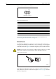
Figure 20: RJ-45 Pin layout
With 10BASE-T/100BASE-TX cables, pins 1 and 2 are used for transmitting
data, while pins 3 and 6 are used for receiving data. Table 9 on page 19 lists the
RJ-45 Pin assignments.
Table 8: Internal DTE pin roles
Pin Role
2TXD
3RXD
4CD
5GND
6DTR
7CTS
8RTS
Pin 9
Pin 6
Pin 5
Pin 1
DB9 Female Pin View
1
8
1
8
RJPIN