
Specifications


Hardware Reference 15
C613-03020-00 REV N
Table 2: System LEDs on all models except Rapier 48w and 48w-B
LED State Function
Power Green The switch is receiving power and the voltage
is within the acceptable range.
Fault Red The switch or manag.ement software is
malfunctioning
1 flash A switch fan has failed. The LED will not
indicate an RPS fan failure).
3 flashes If an RPS is connected, the switch’s PSU has
failed.
4 flashes If RPS monitoring is enabled, the RPS PSU has
failed.
5 flashes If RPS monitoring is enabled, an RPS is not
connected or is not operational.
RPS
1
(Redundant Power
Supply)
1. DC models do not have an RPS connector and the RPS LED will not function.
Green An RPS is connected to the switch.
In use
2
(Rear panel)
2. Not included on the Rapier 48, G6, G6F-SX/SC, G6F-X/SC, or G6F-SX/MT-RJ.
3. Hot swapping is supported by Software Version 2.3.1 or later. AT-AR021(S) BRI S/T, AT-AR021(U)
BRI U, and AT-AR023 SYN PICs can be hot swapped.
Green An NSM is installed, is receiving power, and is
operational. The NSM and its PICs are not
ready to be hot swapped.
Off No NSM is installed, or the switch has not
recognised the NSM.
Swap
2
(Rear panel)
Green The NSM and its PICs are ready to be hot
swapped.
Off The Hot Swap button must be pressed before
the NSM or PICs can be hot swapped, or the
software version does not support hot
swapping
3
.
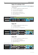
Table 3: Switch port LEDs on the Rapier G6
LED State Function
L/A
(Link/Activity)
Green A 1000 Mbps link is open
Amber A 10 Mbps or 100 Mbps link is open
Flashing Green 1000 Mbps activity is occurring
Flashing Amber 10 Mbps or 100 Mbps activity is occurring
D/C
(Duplex/Collision)
Green The port is operating at full-duplex
Amber The port is operating at half-duplex
Flashing Amber Collisions are occurring on the line